SSA CCS installation
Playing in the workshop continues.
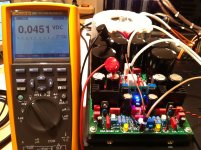
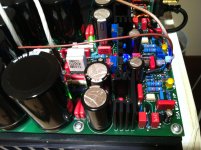
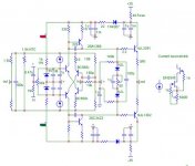
First current source/sink module installed into the left channel, bias set to 200 mA per output BJT, injects/sucks 10 mA to/from the feedback bridge, 11 mA VAS bias current, everything looks OK, super DC stable, output DC offset set to zero, no oscillations whatsoever in a 100 MHz bandwidth sweep in mV range. Very simple upgrade installation, 4 connecting pins soldered to previous trimmers pads, stable vertical position on the mother board.
Playing in the workshop continues.
First current source/sink module installed into the left channel, bias set to 200 mA per output BJT, injects/sucks 10 mA to/from the feedback bridge, 11 mA VAS bias current, everything looks OK, super DC stable, output DC offset set to zero, no oscillations whatsoever in a 100 MHz bandwidth sweep in mV range. Very simple upgrade installation, 4 connecting pins soldered to previous trimmers pads, stable vertical position on the mother board.
Attachments
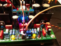
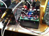
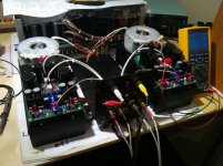
Yesterday's job, firing both CCS upgraded chanells, setting the bias, initial tests performed (clipping, squares, etc) and than listening.
Yeah, completely new level of quality presented, amp simply doesn't want to distort, speakers thermal loading was the limit.
Sound is amazing.
Yeah, completely new level of quality presented, amp simply doesn't want to distort, speakers thermal loading was the limit.
Sound is amazing.
Attachments
Last edited:
Is it advisable we install some sort of CCS instead of the resistors that feed DC off the rails to the Zeners at the SSA bridge in all simpler amps we got? Brings better DC offset stability to all?
Of course, especially if there's regular zener diode present, it would improve zener voltage to be more stable (constant), also PSRR would improve.
If there's TL431 used for +/- 15 V DC potential, than only resistor supplying current from rails is sufficient, since TL431 is monolithic chip precision zener.
Most important if you can do is to replace FB bridge injecting resistors with CCS, that would do the magic trick in the first place.
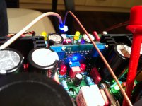
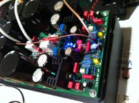
What part you exchanged with your CCS pcbs on photos?
It's OK, will help also the others interested. Four parts encircled were replaced with these CCS-s.
Attachments
Last edited:
So this with signal modulating the working conditions really has an impact..
It sure it does. It's not that I was not aware that any diff amp (LTP or CFE) can handle without constant current source, it's just that I was not ready to go to that track at SSA. Problem was to find enough DC stable CCS to replace a resistor (not thermally dependant), that will not substantially mess and cause extra thermal fluctuations. I had CCS in schematic, see here but these common CCS-s were just not good enough for SSA concerning thermal stability. I knew that it will cost me a lot of time to choose and test the right one. But as usual things go on a hard way. Your sim measurements convinced me that surely I have to go for it and for that I would really like to thank you MiiB.

Well done Andres - Great Achievement,
But it amuse me that you decided against "fetzilla" because it might get too complicated
Thank you Mikelm
I'm sorry I don't understant, can you please explain in what way I decided against Fetzilla. My aims were clear from the beginning, I was searching a suitable amp for my horn speakers, that can also deliver 200 Wrms/ 4 ohm and will use my favourites BIGBT outputs. Fetzilla is very nice amp, probably I will build it in near future, but BIGBT concept and power request just didn't fit in.
TSSA is more easy amp to go, which can be very simple or high performance one as it is in last posts.
I just hope will all be healthy and have opportunity to make many amps in the forthcoming future.
Regards, Andrej
Here's my version. Just slightly under compensated, without the series resistor for the NTC. I'll put it on the real heatsink before any final tweaking. I used TO-92 versions of the DN2540 because I had them.
Sheldon
Super, Sheldon, this will do. Inform us fluently and we'll share experiences and joy.

Can anybody help? My obviously made in China dual tracking power supply has all ics transistors with only part numbers I see no chance to fix it. The 2 pairs of power transistors get bias with oscillation . The device is ok has 2 times 40 volts tracking , 2.5 amps 4 analog meters so the best can do is a new control unit . Tested and verified schematic for a tracking power supply anyone? Without a power supply
with current limiter I do not dare to test prototypes of amps.
I think I found the ultimate solution an all current amplifier no Vas at all. Of course it has a current output. This requires some stuff to compensate the speaker's parameters
but this is not a huge problem.
with current limiter I do not dare to test prototypes of amps.
I think I found the ultimate solution an all current amplifier no Vas at all. Of course it has a current output. This requires some stuff to compensate the speaker's parameters
but this is not a huge problem.
Thank you Mikelm
I'm sorry I don't understant, can you please explain in what way I decided against Fetzilla.
Perhaps it was someone else that said that.
I think my next build with be with separate voltage gain stage & Zero FB follower o/p stage - balanced throughout - I feel like trying a radically different topology
Last edited:
Perhaps it was someone else that said that.
I think my next build with be with separate voltage gain stage & Zero FB follower o/p stage - balanced throughout - I feel like trying a radically different topology
I don't want to spoil your feelings but the biggest nonlinear distortion factor comes from the output stage.
But again, maybe we are a bit scared of distortion ... Some of us.
After PMA mentioned that he rarely exceeds 2V at amplifier o/p recently I checked mine again and it was a similar story - so I'm hoping I can figure something out that will sound good.
I have a medium level of fear regarding distortion - it increases as distortion becomes high order
At present I don't have a fear of class A o/p & o/p chokes - especially as I already have some - but the fear may develop afterwards
So I'm gonna try saying bye bye to 2nd & Hello to 3rd HD . . . Let's see how that sounds
LC,
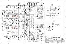
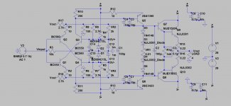
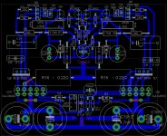
I have received my 2SA1360/2SC3423, so i'm resuming my project on SSA BJT. Below attached are my layout and schematic, could you help me to look through it to see if any problem or improvement could be made. (I'm more concern on the quality of sound due to layout)
SSA BJT made up of 10 transistor, should be rated at rms 50W. The only different between 2 picture is that no thermal compensation in the schematic. (TR & R19)
I'm using single sided board, with brown/red line as a jumper. Red words actually is meant to be terminal block.
I'm not so familiar with PCB boarding program, so its not neat/nice, just basic layout. I want to complete SSA with the best method & effort, so its best if there is many people would assist me in the way ^^
I have received my 2SA1360/2SC3423, so i'm resuming my project on SSA BJT. Below attached are my layout and schematic, could you help me to look through it to see if any problem or improvement could be made. (I'm more concern on the quality of sound due to layout)
There is a question I wanted to ask before : Is there any point adding a 1uF cap at VR1 terminal ? since there is a 100uF across somewhere along.More eyes+brain
SSA BJT made up of 10 transistor, should be rated at rms 50W. The only different between 2 picture is that no thermal compensation in the schematic. (TR & R19)
I'm using single sided board, with brown/red line as a jumper. Red words actually is meant to be terminal block.
I'm not so familiar with PCB boarding program, so its not neat/nice, just basic layout. I want to complete SSA with the best method & effort, so its best if there is many people would assist me in the way ^^
Attachments
Last edited:
LC,
I have received my 2SA1360/2SC3423, so i'm resuming my project on SSA BJT.
Super BJT's, have even isolated case, I'm pleased that the SSA project is again in progress at you.
Is there any point adding a 1uF cap at VR1 terminal ? since there is a 100uF across somewhere along.
No, not needed, but since there's four diodes in series you can add 1uF in parallel to 100uF.
I'm not so familiar with PCB boarding program, so its not neat/nice, just basic layout. I want to complete SSA with the best method & effort, so its best if there is many people would assist me in the way ^^
It's good to start with PCB design once, very knowledgeable, will gain a lot of experiences making your own PCB.
Few remarks on the topic:
- be careful choosing the track's width, always have in mind how many amps will run through
- mechanical layout, heatsinking of outputs and drivers is first step, cause you don't wanna smoke them out
- please read this post and linked one and I suggest you to do the same
This far from me now, please process all info presented and be in touch, regards, Andrej
OK, get it, will add one of it withinl ater, now need to go for some family business.No, not needed, but since there's four diodes in series you can add 1uF in parallel to 100uF.
If i'm not wrong, I use only 2 width in my PCB, one for high current (over 5A), which have roughly 3mm width. and others are lower than 2A, which have 1mm width.It's good to start with PCB design once, very knowledgeable, will gain a lot of experiences making your own PCB.
Few remarks on the topic:
- be careful choosing the track's width, always have in mind how many amps will run through
- mechanical layout, heatsinking of outputs and drivers is first step, cause you don't wanna smoke them out
- please read this post and linked one and I suggest you to do the same
This far from me now, please process all info presented and be in touch, regards, Andrej
As in heatsink, I'm making similar to yours, which is inverted, folded to attach it at below.
As the post you told me to read is about the CCS ? Thinking to integrated into later version, which I want to listen its different.
- Status
- This old topic is closed. If you want to reopen this topic, contact a moderator using the "Report Post" button.
- Home
- Amplifiers
- Solid State
- Simple Symetrical Amplifier