It can can all be done with half the complexity with clever circuitry, thats why that input stage scheme is brilliant if you can get it going. Try a prototype.
So this would actually make a significant difference. So simple measure to a local feedback elevates performance to another level. Really worth to try.

Yeah, interested me too but he's answer was, that's just my way of doing it.Btw what does those cascodes on the emitters of the input pair do ??
Finally someone sees where the main distortion is coming from, the vas. Theres practically no voltage swing at the input pair, the contibution to THD there is next to nothing.
Me see too.

Input pair's collector current dynamically differentiate just for a base drive current of the VAS (uA's), still there's proper bias for both of them. Very nice.
Last edited:
Thats so called hawksford, offcourse it would improve things, how much Im not sure, more complex though, better than baxandall - not sure but I think not, baxandall however takes care of another of the this designs hiccups to a large extent although this may not be so apparent. Intergrating the input with the vas to save on 2 active components is excellent if it can succesfully be pulled off, I failed many years back but that was before simulators, lets see if KT can pull it off.
I might be tempted to make a prototype, if I had a soldering iron. I'm currently negotiating with Bear to see if I can earn an Aoyue 936...
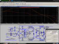
Here's an idea about bias. This would keep the VAS quiescent under control so the output stage quiescent is more stable, and there's no need for degeneration to control the tempco. They could be adapted to provide VAS protection. Furthermore, no B-E resistor, so less distortion. Another thing Shunt compensation lends itself to... I wonder how much effect VAS cascodes will have now. Now all that's left is to get the input stage thermally stable.
The bias transistors are given an extra Vbe drop to pull them out of quasi-saturation, reducing B-C leakage.
I'm not sure about the input stage. The input cascodes are not necessarily helpful when you consider the feedback buffers aren't cascoded. Perhaps they should be RC'd. This is too close to the BC voltage limits anyways.
I'm guessing Q10 and Q9 are what you're calling "emitter cascodes". I see them as an NTP for "no-tail pair". Or, Rush Cascode. I think calling them a cascode misses the point though. In this design they are very aptly described as "feedback buffers". That is their main purpose. They keep from injecting VAS drive into the feedback loop. However this is only mostly achieved as the Vbe variations have the same effect. Perhaps the circuit could be faster if I got rid of the feedback buffers and lowered compensation, after all the VAS has been improved.
Attachments
This VAS mod is interesting... I could decrease the input stage current way down and give the amp a very large input impedance, as the input bias current would be very small. Maybe it could be a HF electrometer if I used a buffered VAS...
The only problem with the above circuit is that it must be AC coupled.
The only problem with the above circuit is that it must be AC coupled.
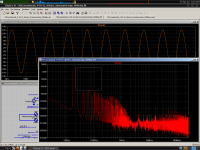
Didn't catch you. Here is the FFT, since DC drift overwhelms LTspice's .four calculation at these levels. Taken at 1k and 20k.
Attachments
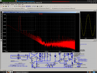
All tests are made at 12V into 6R.
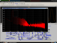
Without feedback buffers...
Also notice the input and output stage RCs which each reduce distortion be a few dBs.
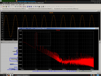
Without feedback buffers...
Also notice the input and output stage RCs which each reduce distortion be a few dBs.
Attachments
I found the SSA topology in the schematic of an old amp ( 1995) combined with what was dubbed Isolated Current Amplifiers as VAS. It should be noted the maker of these amps is bankrupt... these had reportedly been very sensitive to complex loads thus sarted to oscillate and burned off...
Grand master Abrahamson (Electrocompaniet) said in an interview that improper grounding causes far more thd then fine tuning of topology could compensate.
Abrahamson stressed local feedback instead of global NFB is in any case preferable. In practice that means the topology theorists are on the wrong track.
I have now an older paper that investigates distortion mechanism in terms of grounding.
Using 2 transformers and 2 rectifiers instead of one symmetric, with grounding at one reference point as power supply yields astonishing improvements of measured thd
I thought this was fairly common knowledge.
First read about this from Russ Andrews when Paul Hynes was doing design work for him in the late eightees and early nineties and I have been using this method ever since. Several design's presented here use this kind of power supply arrangement including those from Hugh Deans & Peter Daniels.
I am often amazed that some really clever designs presented here use such basic power supplies. I heard the opinion expressed many years ago by an audio professional that 90% of a good sounding amplifier design comes down to power supply design. This may be an exaggeration but I think it makes a useful point given how little attention this subject often receives.
For instance - How many here have done an A / B comparison between a similarly specified torroidal and EI power transformer ? Be prepared to be amazed.
mike
I did...and wow I am using shielded EI....I thought this was fairly common knowledge.
For instance - How many here have done an A / B comparison between a similarly specified torroidal and EI power transformer ? Be prepared to be amazed.
mike
I found however a simple ring of copper band around the transformer does as good as a magnetic shield.
Neither grounding nor power supply effects can be properly simulated.
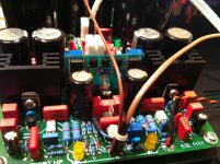
Another design objective is to keep the high current power section of an amp off the PCB. Its simple yet measurable effects of a spacing of 5-10 cm are amazing.
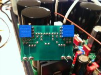
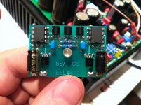
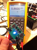
Today's playing in the workshop 
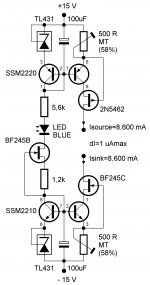
8,600 mA exactly (0,8600 V/100 ohm) no joking around
8,600 mA exactly (0,8600 V/100 ohm)
no joking around Attachments
I found the SSA topology in the schematic of an old amp ( 1995) combined with what was dubbed Isolated Current Amplifiers as VAS. It should be noted the maker of these amps is bankrupt... these had reportedly been very sensitive to complex loads thus sarted to oscillate and burned off...
Grand master Abrahamson (Electrocompaniet) said in an interview that improper grounding causes far more thd then fine tuning of topology could compensate.
Abrahamson stressed local feedback instead of global NFB is in any case preferable. In practice that means the topology theorists are on the wrong track.
I have now an older paper that investigates distortion mechanism in terms of grounding.
Using 2 transformers and 2 rectifiers instead of one symmetric, with grounding at one reference point as power supply yields astonishing improvements of measured thd
Truth about grounding, there's theory and there's experiences but in spite of all that in anyway worth to experiment a little when an amp is assembled in a case. Repeatability is guaranteed than - serial production. I always produce double battery pack sort of power supply, GND star meets in amp's PCB. If stereo, channel's mutual GND meets at the inputs.
I saw that you found quite impressive solution for your inverting amp, 60° thermal equilibrity and all that. Are you deeply in a prototyping job already? Practical results?
Regards, Andrej

- Status
- This old topic is closed. If you want to reopen this topic, contact a moderator using the "Report Post" button.
- Home
- Amplifiers
- Solid State
- Simple Symetrical Amplifier