skipper said:I've measured R17 and R27 and got 36.6V and 35.5V respectively.
That also seems fine. So the tubes are setup and working. Something somewhere is killing the signal it seems.
Hi All,
I drew up what the schematics that came with my transformers. I will try to scan them tomorrow and post them. In the mean time I drew them up. So may be I now see the issure.
The power transformer instructions says:
120 Volt primary: connect the two primary windings in parallel.
Black and green connect together.
Black/white adn Grean/white connected together.
I think I did this OK.
From the XPWR049 exaple in the previous mail, it shows the 6.3V and 5V to have a common. The PPWR059 I am using has two 3.15V leads and a CT and two 2.5V leads and a CT (See attachment). I connect two leads of each voltages to the board and just tied back the CT. Should I have connected both 2.5V together and the 3.15V together and connect each CT to the board? From my drawing is shows that perhaps the brown and yellow are switched? I will try to call Edcor tomorrow.
Thanks!
Attachments
Hi All,
I drew up what the schematics that came with my transformers. I will try to scan them tomorrow and post them. In the mean time I drew them up. So may be I now see the issue.
The power transformer instructions says:
120 Volt primary: connect the two primary windings in parallel.
Black and green connect together.
Black/white adn Grean/white connected together.
I think I did this OK.
From the XPWR049 exaple in the previous mail, it shows the 6.3V and 5V to have a common. The PPWR059 I am using has two 3.15V leads and a CT and two 2.5V leads and a CT (See attachment). I connect two leads of each voltages to the board and just tied back the CT. Should I have connected both 2.5V together and the 3.15V together and connect each CT to the board? From my drawing is shows that perhaps the brown and yellow are switched? I will try to call Edcor tomorrow.
Thanks!
Attachments
skipper said:Hi All,
Should I have connected both 2.5V together and the 3.15V together and connect each CT to the board? From my drawing is shows that perhaps the brown and yellow are switched? I will try to call Edcor tomorrow.
Thanks!
No, the center taps aren't used. Why don't you measure the windings? Pull the tubes first.
According to the diagrams that you got from Edcor your transformers are wired correctly. The colors on your Edcor OPT's are different from mine even though they are the same model transformer. Maybe Edcor doesn't know the convention that has been used for the last 100 years! Your voltage readings confirm that the power transformer is not the source of this problem.
I am assuming that you connected your speaker directly to the yellow and white wires, not the blue and black like I originally stated. Connect the wires directly to the speaker without any connection to the PC board.
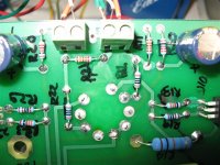
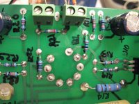
Would it be possible for you to post a picture of the components on your board that is good enough that we can read the resistor colors. I tried again to check the components in your previous picture but the colors aren't clear. If you have a picture that is clear enough, but too big to post, email it to me. A picture of your input wiring may be a good idea too.
I am assuming that you connected your speaker directly to the yellow and white wires, not the blue and black like I originally stated. Connect the wires directly to the speaker without any connection to the PC board.
Would it be possible for you to post a picture of the components on your board that is good enough that we can read the resistor colors. I tried again to check the components in your previous picture but the colors aren't clear. If you have a picture that is clear enough, but too big to post, email it to me. A picture of your input wiring may be a good idea too.
Here is a scan of the Edcor info that came with the transformers. I spoke with Edcor this morning and they said that the BRN 5V and Yellow 6.3V wiring is correct. They said they change the colors because the 6.3V wires come out on the same side of the transformer as do the 120V black wire. Some people had confused the black and brown wires because they look alike. They have asked their wire manufacture for a lighter color brown wire but they always get the dark brown.
George, I did connect the speaker directly to the yellow and white wires. I will post some pics of the components later on this evening.
George, I did connect the speaker directly to the yellow and white wires. I will post some pics of the components later on this evening.
Attachments
Doc Jr 8156 said:Can someone tell me the part numbers for D1 and D2? Thanks.
Fairchild ISL9R8120P2 Mouser 512-ISL9R8120P2
skipper said:They said they change the colors because the 6.3V wires come out on the same side of the transformer as do the 120V black wire. Some people had confused the black and brown wires because they look alike. They have asked their wire manufacture for a lighter color brown wire but they always get the dark brown.
This is true...I had to look twice. Do they not own any green wire? Swap one, admittedly bad, confusion for another less-bad-but-still-kinda-bad confusion.
Those FREDs are the subject of many threads on this forum. Their (unspecified) avalanche energy capability has diminished at some point in the recent past and they are now highly unreliable in this design. The Fairchild Stealth diodes are specifically designed to handle large avalanches and work perfectly.
They are still not available from Digikey in small quanities. Note that you do not need these diodes in the SSE if you are using a tube rectifier.
They are still not available from Digikey in small quanities. Note that you do not need these diodes in the SSE if you are using a tube rectifier.
rknize said:Something somewhere is killing the signal it seems.
There was a case last November where a couple resistors got swapped due to a typo on the schematic. The end result was really low gain and uselessly quiet output. George fixed the schematic, and I can't imagine the same problem could have possibly happened again, but...
Here's a post kinda in the middle of the thread where George finally recognized what was wrong:
http://www.diyaudio.com/forums/showthread.php?postid=1667364#post1667364
Here's a post kinda in the middle of the thread where George finally recognized what was wrong:
I took a careful look at the photo of skippers board and don't believe that is the case here, but that is the reason that I asked for a clearer picture.
Hi All,
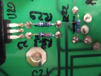
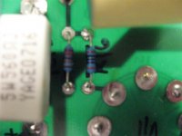
I measured R16 and R26 on the board and read 100 ohms. I measured R15 and R25 and read 220 K ohms. When I was soldering them on the board I had also measured them first and wrote down the right numbers. I am attaching several pictures on my components. Sorry about the bad quality but my camera is not very good. Let me know if you want to see something specific and I can take more.
I measured R16 and R26 on the board and read 100 ohms. I measured R15 and R25 and read 220 K ohms. When I was soldering them on the board I had also measured them first and wrote down the right numbers. I am attaching several pictures on my components. Sorry about the bad quality but my camera is not very good. Let me know if you want to see something specific and I can take more.
Attachments
- Status
- This old topic is closed. If you want to reopen this topic, contact a moderator using the "Report Post" button.
- Home
- More Vendors...
- Tubelab
- simple se build