Considering that you said that you are having difficulty getting the tube in to the socket, that initially you could not get the tube to light up, that the tube does not sit flush and that there appears to be something obstructing the tube getting in to the socket, then I think you must assume that the problem is with the socket. Perhaps some of the pins of the tube are not making contact. I would say that you may have used too much solder while putting the socket on the board, or you have a bad socket. I think it is worthwhile checking your sockets before soldering them to a board as some do have manufacturing defects, and they are very difficult to unsolder.
If you cannot get the tube in the socket you will have to fix it somehow. Either clean out the pin holes with a fine drill or similar, or replace the socket...
Best of luck!
Chris
If you cannot get the tube in the socket you will have to fix it somehow. Either clean out the pin holes with a fine drill or similar, or replace the socket...
Best of luck!
Chris
sailWickedFast:
I don't see any order from Rhode Island. There have been only 6 board orders in June. The only one from the east coast came in last night. It goes to Virginia.
skipper:
The likely possibility is that the tube is not making contact in the socket. This can be determined by taking a few voltmeter readings on the board while it is powered up.
Connect the black lead of your voltmeter to ground. Set the meter to its highest DC voltage range. With the amp on and warmed up, touch the red probe to the right hand end (closest to the 12AT7) of R29. The voltage should be between 150 and 250 volts. Repeat the measurement with the left hand end of R13.
If these points measure 400 volts or over the 12AT7 is not making contact or is bad.
Just ordered a Simple SE board for my first tube amp project.
I don't see any order from Rhode Island. There have been only 6 board orders in June. The only one from the east coast came in last night. It goes to Virginia.
skipper:
The likely possibility is that the tube is not making contact in the socket. This can be determined by taking a few voltmeter readings on the board while it is powered up.
Connect the black lead of your voltmeter to ground. Set the meter to its highest DC voltage range. With the amp on and warmed up, touch the red probe to the right hand end (closest to the 12AT7) of R29. The voltage should be between 150 and 250 volts. Repeat the measurement with the left hand end of R13.
If these points measure 400 volts or over the 12AT7 is not making contact or is bad.
With a username like yours I figured your location had to be Boston or somewhere in New England. Hopefully, George will get you your board wicked fast
you forgot pissa...
Skipper - can you get a picture of the tube & socket?
skipper said:I don't think I got solder in the pins. If I look straight down into the socket, some holes look open while some look like there is some metal in there actually push against the pin. Unfortunately I do not have another old tube to work the socket in and out a few times. I actually have used quite a bit of force trying to get the tube in.
The tube seems to be lite, shouldn't I get some kind of sound out?
There could be some other pins not making contact. How far are you getting it in there? A picture would be helpful, specially of the base of the socket. The pins on these seem to be tinned, so solder will happily flow up into them if enough is applied. You have to use just enough where it starts to appear on the other side of the PCB but no more.
I don't see any order from Rhode Island.
The reason that I brought it up is that people may have 2 addresses, which is OK, but too often people move and never update their Paypal address. The board then checks in to the US postal service's black hole never to be seen again.
Skipper - can you get a picture of the tube & socket?
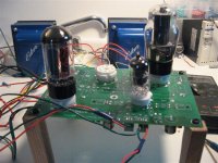
If you post a picture of the components side of the board we can look it over for ovbious issues. I studied the pictures that you posted previously and the only questions that come up are the colors of the wires going to the back of the board. I see yellow wires connected where the green ones should go. It they are extensions of the green transformer wires, then OK.
I have used the type of sockets that you have, and I did receive a bad one once. The tube wouldn't go into it at all, because some of the holes in the ceramic were too small. Replacing the tube socket is not easy either. I can explain the proceedure it it gets that far.
I can explain the proceedure it it gets that far.
I've watched a lot of talented tech's do things to components that I would never consider.
I would bet that they would think - I can cut the legs off of that socket and remove the pins a lot easier...
Hopefully it won't come to that.
I can cut the legs off of that socket and remove the pins a lot easier...
If the main objective is to save the board and remove the socket, that's exactly what I do. Carefully cut through each pin with sharp cutters, remove the socket, then unsolder each pin one at a time, then clean out the holes with solder wick.
It is possible to remove the socket in its entirety by heating the back side of the board around the socket with a good heat gun. Not enough heat and you will rip plating off of the board when you yank the socket. Too much heat and you will burn the board. There are speciallized heat guns made for this purpose. I have a Hakko on my desk at work that is made for removing components. It has attachments for SMD's too. It costs about $600, so it is not in reach of many hobbiests. I wouldn't recommend this unless you have done it before.
There are speciallized torches like the Weller Pyropen that can be used to remove components. I have one and it works on large SMD's but I don't know if it has enough heat for these sockets.
If I want to salvage some sockets from my dead proto boards, I use an ordinary propane torch. Grab the board with a pair of Vice Grips. Heat up the back side of the board until it starts to smoke, then whack it on the ground. almost all of the parts will come off! This procedure is NOT recommended here, it must be done outside, hot solder will fly, and not all parts will survive. The ceramic sockets do pretty well though. The board however is toast.
Hey Guys,
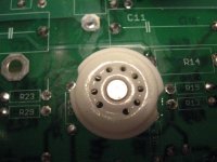
Here are a couple of pictures of the socket and component side of the board. The tube will not sit flush. Now I remember that when I first got my tubes, I did try to fit the tube on the socket. It did go in but I had to apply a lot of pressure.
George, according to the information sent with my PWRT, the yellow wires are for the 6.3V and the brown wires for the 5V.
I will not get a chance to measure the voltages until tomorrow. George, you said "touch the red probe to the right hand end (closest to the 12AT7) of R29. The voltage should be between 150 and 250 volts". Do you mean to measure right at the socket pin (leg)?
Thanks,
skipper
skipper said:Here is another pic.
Wow, you're a lucky man, looks good.
I can't wait till I order mine and get started on it.
The KT88 looks magnificent.
You'll need to post some finished shots of it in the dark with the
tubes a'blazing.
I can't make out anything obviously wrong from the pictures. Your soldering looks OK, though a closeup of the base of the socket near the trouble pins might help. Another idea is to find or make a tool that has the same diameter of the tube pin that you can push into the socket holes and clear them.
tubelab.com said:sailWickedFast:
I don't see any order from Rhode Island. There have been only 6 board orders in June. The only one from the east coast came in last night. It goes to Virginia.
tubelab.com said:
The reason that I brought it up is that people may have 2 addresses, which is OK, but too often people move and never update their Paypal address. The board then checks in to the US postal service's black hole never to be seen again.
Yup, that's me
") I'm in the DC suburbs doing contract work for the Defense Department for now, but home is where the heart is as they say...
I'm in the DC suburbs doing contract work for the Defense Department for now, but home is where the heart is as they say...Can't wait to get the board and get it populated. Started pulling my old rig out of storage, Bang and Olufsen turntable, etc. Will sound so sweet through tubes

boywonder said:
Welcome Sailwicked: There is tons of info here for the Tubelab simple SE, including support from Tubelab George himself if you have questions.
With a username like yours I figured your location had to be Boston or somewhere in New England. Hopefully, George will get you your board wicked fast
Thanks! Yes, this site looks like an incredible resource for sure. I'm wicked psyched now
Hi All,
Ok, I finally got my 12AT7 tube to sit flush on the socket. I bought an old 9-pin tube to try to work it in a few times but I was having the same problem of trying to get it in.
So, what I did is I stripped back some 20ga solid wire and worked it in each socket pin hole. I also tried 18ga but could not get it to fit in all the holes. I must have loosened them up a little because I did get the tube on with still a lot of pushing effort.
So, know all my tube are lite but still no sound. I measued the R29 voltage and it was 212V and I measured the R13 and it had 227V.
Any other voltages I should measure? What should the OPT voltage be going to the speakers? I hope it is just something silly I forgot to do, may be grounding something?
Thanks,
Skipper
- Status
- This old topic is closed. If you want to reopen this topic, contact a moderator using the "Report Post" button.
- Home
- More Vendors...
- Tubelab
- simple se build