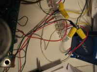
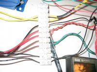
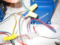
Ok guys, I checked out every resistor and they all look correct. R2 and R4 did not give me a stable reading but as state previously, they are connected to the caps and may not give the correct values. I've attached a spead sheet of my values.
I even tried a different RCA cable for my input and still very low volume. Next I think I will remove the current limiter from the PWRtran CT and see if that makes any difference. At this point I am stuck! Not sure what else I should measure or check?
I even tried a different RCA cable for my input and still very low volume. Next I think I will remove the current limiter from the PWRtran CT and see if that makes any difference. At this point I am stuck! Not sure what else I should measure or check?
Attachments
I have 432 V going to my B+ of my OPT, what should the output voltage be for speakers?
The red wire on the OPT is for OPT is for B+ and the Blue for Plate. What voltage should the Plate be?
Does the music signal to to the OPT through the Plate correct and to the blue wire on the OPT?
The red wire on the OPT is for OPT is for B+ and the Blue for Plate. What voltage should the Plate be?
Does the music signal to to the OPT through the Plate correct and to the blue wire on the OPT?
skipper said:I have 432 V going to my B+ of my OPT, what should the output voltage be for speakers?
Your B+ sounds reasonable. With one side of the OPT secondary grounded, you will measure 0V on the other side when there is no input signal to the amp. If you feed the amp a 60Hz signal (with a speaker connected, of course) and put a decent AC meter on the secondary, you'll measure some volts. The value is not terribly important or interesting.
skipper said:The red wire on the OPT is for OPT is for B+ and the Blue for Plate. What voltage should the Plate be?
The blue wire for the plate should read roughly 10V lower than B+...but it really depends on your bias current.
skipper said:Does the music signal to to the OPT through the Plate correct and to the blue wire on the OPT?
I'm not sure what you mean by this. The amplified signal would appear on the blue OPT wire, but remember that it is sitting at over 400VDC. Don't try to put a scope on it!
Hi Russ,
I am trying to verify if my OPT are working correctly and I am not sure how to isolate the problem from the board or the OPT.
If both B+ and Plate voltages are OK, then I would think that I should get loud music out the OPT speaker secondaries, if the OPT are good.
If the OPT are good, then it must be the music signal coming into it that is bad?
I have not measured the plate current but I will do that later this evening.
I spoke with a tech at Edcor to ask about how to test the OPT. They said that with 354V AC RMS that the speakers output is 14V RMS. I assume that is AC voltage like what you mentioned.
I wonder if you've somehow shorted the signal to ground somewhere in the amp. Here's a quick and easy game we can play. Unplug your amp and pull the tubes out of the sockets. Get out your meter. Use a clip lead or something and attach one probe to ground. Use the other probe set to measure DC resistance (ohms) and see what you've got from each pin of the tube sockets. Maybe I'll go pull out my Simple SE and try the same thing. Of particular interest would be the cathode, grid, and plate pins for each tube (1,2,3 and 6,7,8 on the 12AT7 - 3,4,5,8 on each power tube socket).
Ok, maybe not as educational as I had hoped. Parts which are connected to caps or the CCS won't give you any kind of stable or useful reading. Anyway, here's what I saw:
12AT7
1 (plate) wacky reading, connected to CCS
2 (grid) 220.7K ohms (R11 + R12)
3 (cathode) 221 ohms (R10)
6 (plate) wacky reading, connected to CCS
7 (grid) 222.4K ohms (R21 + R22)
8 (cathode) 220.1 ohms (R20)
Right power tube
3 (plate) connected to PSU caps through the OT
4 (screen) same as plate
5 (grid) 223.4K ohms (R15 + R16)
8 (cathode) 0.813K ohms (R17, ~810 ohms in my case)
Left power tube
3 (plate) connected to PSU caps through the OT
4 (screen) same as plate
5 (grid) 223.3K ohms (R25 + R26)
8 (cathode) 0.812K ohms (R27, ~810 ohms in my case)
Ty,
Thanks for taking those readings. I will try to measure them tonight and compare data. The only thing I managed to do this weekend is measrue the Plate voltage from the OPT. Both channels measured 436V.
I would have to say that my OPT are OK and my problem lays with something on my board or I have the darn thing hooked up incorrectly.
Something is wrong here that is not obvious to all of us onlookers. I know how frustrating it is to have spent a lot of time and money on a project and not be able to enjoy it.
I can offer this suggestion. If you want to send me your board, I will test it, and fix it if needed. All it will cost you is postage. At least this way it will be possible to eliminate the biggest variable.
There have been a few simple SE's that had start up issues, but all of them have been solveable through this forum. This one has gone on far too long. Just send the board, no tubes or transformers. If you want to do this, email me for details.
So far this has been necessary only twice. Both boards were Tubelab SE's. One of them had nothing wrong with it, and the other one.....
I don't have the time to do this very often, and fortunately it is not often needed. I have a feeling that this board is OK since all of the important voltages are OK. Unfortunately it is hard to troubleshoot something that is far away. I can test the board in few minutes if I can find my test fixture.
I don't have the time to do this very often, and fortunately it is not often needed. I have a feeling that this board is OK since all of the important voltages are OK. Unfortunately it is hard to troubleshoot something that is far away. I can test the board in few minutes if I can find my test fixture.
Ty,
Here are the numbers I got tonight. I did get some numbers that were different than what you measured. I will look a bit deeper into it.
George, I think I will take you up on you offer and ship my board out to you. I thought I doubled and tripled check everything as I assembled my board but maybe I missed something.
Thanks!!
12AT7
1 (plate) wacky
*2 (grid) 3.93 K ohms (R11 + R12)
*3 (cathode) 220.9 ohms (R10)
6 (plate) wacky reading, connected to CCS
*7 (grid) 3.94 K ohms (R21 + R22)
8 (cathode) 220.1 ohms (R20)
Right power tube
3 (plate) connected to PSU caps through the OT
4 (screen) same as plate
5 (grid) 221K ohms (R15 + R16)
8 (cathode) (R17, 562~ ohms in my case)
Left power tube
3 (plate) connected to PSU caps through the OT
4 (screen) same as plate
5 (grid) 220 ohms (R25 + R26)
8 (cathode) 0(R27, ~560 ohms in my case)
skipper*2 (grid) 3.93 K ohms (R11 + R12).........Ty_Bower 2 (grid) 220.7K ohms (R11 + R12)
I think we could be on to something here. The grid resistance should be about 220K ohms, however you could just be measuring the resistance of your source. Disconnect the input wiring and take a new reading. If it is now 220K the reading is correct and you are measuring the resistance of your source. 3.9 K ohms could be normal for the output of a solid state device, or it could indicate a problem.
- Status
- This old topic is closed. If you want to reopen this topic, contact a moderator using the "Report Post" button.
- Home
- More Vendors...
- Tubelab
- simple se build


