skipper said:I do not have a volume control connected so is that my problem? R11 and R21 (220K) I believe control the volume if no volume pot is used correct? I do have a 50K volume pot that I purchased from I think Mouser. I did not add a volume pot because I plan on connecting a preamp at a later time (with a phono input).
A while back, he did not have the volume pot installed. I don't know if he ever connected it...
If he had the 50k pot on there, we should see more like 40k on the grid unless he has the pot hooked-up wrong and turned down.
The wiper goes to the grid, so it it possible to have zero ohms from grid to ground with the volume pot all the way down. If a source device is connected you will be measuring its output resistance, which could be low on an iPOD.
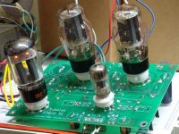
skipper said:Here are a couple of pictures of my board. I still have to add the coupling caps. I plan on running it on a test bench. The inputs and spreaker jacks, where should I run the ground to these for the bench test? Do I just run them to the ground on the power connector?
Also, I got the currently limiters from mouser, so these should come off the fuse and to the power transformer?
Thanks,
Skipper
You want to run the grounds all to some point. You get to choose the point but there are some rules
1) All AC powered devices should have the chassis grounded to the green power cord with as short as practical ground connection wire. (Using a short wire minimises that chance of it being broken or damaged. it's purely a safety issue.))
2) This chassis ground should connect to the signal ground at only one point. (This rule effects the sound, #1 addresses safety.)
I like to use the center tap of the power transformer as the signal ground point. and then conect that ground point to the chassis ground point.
You will notice both of these rule are broken on many (all?) older amps. If you look at older 1950's Fender guitar amps they grounded everything, input cable shields, returns from speakers, you name it to the steel chassis. Now days they use insulating washers on the jacks, keep signal and chassis ground seporate and follow the rules. The newer stuff is built better no matter what they say.
I don't use a 100% star ground. Each sub-assembly like a PCB or turret broad will have a ground bus and then the PCB or turret board is grounded to the common signal ground point. I think it adds to much wire to run every last resistor and cap all the way back to the common ground. IMO that would be extreme and only justified in very high impedance circuits like inside of the cavity in an electric guitar.
tubelab.com said:
The wiper goes to the grid, so it it possible to have zero ohms from grid to ground with the volume pot all the way down. If a source device is connected you will be measuring its output resistance, which could be low on an iPOD.
Oops...brainfart. You're right.
Hi All Thanks for all the input.
I've been working late and taking care on my new born but I manage to take a another reading. The 3.9K Ohm measured for 12AT7 pin 2 and 7 where because I had my input device hooked up. Sorry about that! The new readings I took were pin #2- 220.7Kohm and pin #7-220.8Kohm.
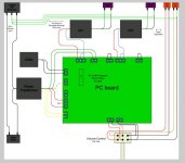
Everything I believe is correct, I have my set up as in the attachment minus the volume pot. I do not have one in place. Should I try triode with CFB to see if there is any difference?
Tonight I am going to look over everything one more time and if I cannot find anything I will send it out to George. I don't think I have my OPT wired incorrectly, previous post I show a pic of how things are hooked up.
I've been working late and taking care on my new born but I manage to take a another reading. The 3.9K Ohm measured for 12AT7 pin 2 and 7 where because I had my input device hooked up. Sorry about that! The new readings I took were pin #2- 220.7Kohm and pin #7-220.8Kohm.
Everything I believe is correct, I have my set up as in the attachment minus the volume pot. I do not have one in place. Should I try triode with CFB to see if there is any difference?
Tonight I am going to look over everything one more time and if I cannot find anything I will send it out to George. I don't think I have my OPT wired incorrectly, previous post I show a pic of how things are hooked up.
Attachments
I will send it out to George.
I got the board on Friday. I looked it over and didn't see anything obvious. I was gone for most of Saturday. I spent some time today doing some testing on my P-P amp. I am clearing some bench space to hook up a Simple SE tonight and may get your board hooked up tonight. If not it will be one evening during the week, depending on what time I get home from work.
I have a built board that has been kicking around here for about two years from an unfinished amp, and another that may or not work. I plan to hook up the good one to verify the set up, then test the other two. I will post the results when completed.
While many of us were enjoying a little vacation on Upgrade Island (did anyone notice that there were no tubes on the island) Skippers Simple SE arrived. I connected it up an it was indeed dead, very dead. I could not hear anything in the speakers with the volume pot up full.
I can honestly say that I have never seen this happen before, and a thousand forum posts would not have ever figured it out. I must add a warning in the construction manual to cover this one.
The PC board uses "plated through holes". This means that there is metal plating inside each hole to connect the top and bottom of the board together. When the wires on those big Auricaps were fatter than the holes in the PC board, Skipper enlarged the holes, destroying the connection. The coupling caps were there on the board, but not connected up. This is why all of the DC voltages and ohm meter readings were correct.
When I make a prototype PC board I do not have the ability to do plate through holes. On these boards you must solder each component on both the top and bottom of the board. I removed both of the Auricaps, stripped back an additional 1/8 inch of insulation and reinstalled them by soldering them on the top and botom. I have used this technique on one of a kind and prototype boards for years, and none of these boards has ever given me any trouble so I believe that this repair should last forever. My Lexan Tubelab SE still has the original "proto" board in it with all the parts soldered on both sides. (I can't destroy the original)
I must say that you must never attempt to enlarge the holes in any commercially purchased PC board unless the board has ALL of the traces (and any metal) on ONE side of the board. Most PC boards use the via and component holes to make connection from one side of the PC board to the other. Many boards now have traces inside the board itself (multi layer construction) and any drilling on these boards will render them unrepairable.
I listened to the repaired Simple SE for 3 CD's on Sunday evening using my well worn pair of Chinese 6L6GC's, then unhooked it and packed it up. It is in the hands of the USPS right now.
Yeah, that would have been a tough one to guess for sure. I have to say that these boards are quite durable. The only damage I've done during soldering/desoldering on one of my TSE boards was when I tried to jam binding posts into holes that were too small (meant for small resistors). The solder couldn't wick through and so the posts were only soldered to the pad on the back. When I tightened the screw the pad twisted right off. Ooops. Oh well, easy to fix.
George,
I would like to thank you again for taking time to check out my board. It was a lesson learned, I hope it help some other newbie from making the same mistake.
What should have been the proper way of connect up the Auricaps. Should I have cut out some of the strands of the wire to make it a smaller diameter to fit the hole in the board or enlarge the hole and solder both sides like you did? Is one method favored over the another?
I look forward to receiving my board so I can finally get down to listening to some music!
Skipper
I am not sure which auricap you used but the leads on mine fit, although rather snug. I just had to really twist them tight and also take my time when threading it through the hole. You should have fun with this board.George,
I would like to thank you again for taking time to check out my board. It was a lesson learned, I hope it help some other newbie from making the same mistake.
What should have been the proper way of connect up the Auricaps. Should I have cut out some of the strands of the wire to make it a smaller diameter to fit the hole in the board or enlarge the hole and solder both sides like you did? Is one method favored over the another?
I look forward to receiving my board so I can finally get down to listening to some music!
Skipper
I have often had to twist and re-twist braided wires to fit properly into a through hole connection. It just takes a little patience and practice. I'm glad George was able to find your problem and fix it for you.
Have fun with the SSE - and don't forget that there are a bunch of tubes you can use...
Have fun with the SSE - and don't forget that there are a bunch of tubes you can use...
Should I have cut out some of the strands of the wire to make it a smaller diameter to fit the hole in the board or enlarge the hole and solder both sides like you did?
I use the "thin the herd" method. I cut the wires a bit too long, then strip and cut off enough strands to allow for fitment. Thin I tin the wires with just enough solder to very lightly coat the wires. Then I strip back another 1/8 inch of insulation and then re-tin the wire. This leaves a step that sits on the top of the board wile the thinner part goes through.
I am not sure which auricap you used but the leads on mine fit, although rather snug.
I don't remember either but the wires were FAT. They were way to big to fit the holes in the PC board.
The board sounded nice even with my "lightly toasted" Chinese 6L6GC's:
Attachments
One channel not working
Hey All,
After a long journey, I finally got to hear music through my amp. It soulds good through my cheaper test speakers. I've still have not hooked them up to my better speaker.")
The bad news is that only one channel is working the T2-PRI.I've changed tubes position and no difference. I've changed speakers and it follows the bad channel. I change OPT positions and it follows the bad channel.
I measured the B+ on the T2 and it was 421 and the Plate was 426 volts. Before I start poking around any thought on what other test to do?
Skipper
Hey All,
After a long journey, I finally got to hear music through my amp. It soulds good through my cheaper test speakers. I've still have not hooked them up to my better speaker.
The bad news is that only one channel is working the T2-PRI.
I've changed tubes position and no difference. I've changed speakers and it follows the bad channel. I change OPT positions and it follows the bad channel. I measured the B+ on the T2 and it was 421 and the Plate was 426 volts. Before I start poking around any thought on what other test to do?
Skipper
OK, we know the board works. What's different between your setup and mine?
The tubes are one difference. You already swapped the output tubes, the rectifer must be working, so that leaves the 12AT7 (or the socket connections). The operation of the 12AT7 can be easilly verified without swapping it. Using a voltmeter with the black lead connected to ground, measure the voltage on the leads of the coupling caps (C11 and C21) that are visible from the top of the board. There are two leads on each cap. One lead should have about zero volts and the other lead should be about 200 volts. A reading near 400 volts indicates a problem in the 12AT7.
Another difference is the source. The simplest test here is to wire the working and the non working channels together. Temporarilly run a small wire between the outer two terminals on the input connector. (pins 1 and 5). This creates a mono connection. If both (or neither) channels work then there is a problem in your source wiring.
The third difference is the OPT's and their wiring. You indicate a B+ voltage of 421 volts and a plate voltage of 426 volts. This is highly unlikely. The plate voltage should be lower than the B+ voltage. take a voltage reading at R17 and R27. The readings should be similar and from 30 to 40 volts.
Hi All,
I managed to do the test that George recommended.
At C21 I measured 220 V.
At C11 I measured 233 V.
I think this test is OK.
At R17 I measured 35 V.
At R27 I measured 36 V.
I think this test is OK.
I connected a jumper across the pins 1 and 5 on the input and both channels worked, very bad but they worked. So, if I understand George correctly, it is source wiring? This is my input wiring or input jacks correct? I wonder is I should buy another 12AT7, the one I am using seems really faint but I dont remember if this is how is always been.
skipper
So, if I understand George correctly, it is source wiring?
That is what it sounds like.
You said that without the jumper one channel worked. Verify this. Then disconnect the input wiring on the dead channel from the board. Then move the wiring from the live channel over to the input connections on the board that you just vacated and verify that the other channel works. If so, then there is a problem in the input wiring, or the source.
- Status
- This old topic is closed. If you want to reopen this topic, contact a moderator using the "Report Post" button.
- Home
- More Vendors...
- Tubelab
- simple se build