Yes I ordered a pair of GB150ABS but it's now a GB150S. Don't know about the difference, looks the same. Greg tells me it has more grounds and a ground ripple reduction layout for lower noise.
I think they're very quiet now but he's a perfectionist.
I've yet to see the chassis.
I think they're very quiet now but he's a perfectionist.
I've yet to see the chassis.
GB150D finished and playing
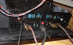
SKA GB150D finisished, view from the back. Vampire rca connectors with dyi belden 89259 cable (Jon Risch) Vampire connectors, Cardas CCGG binding posts (Sonic Craft), Volex power cord (Carlton-Bates) all mounted in a designbuildlisten chassis. I've left the back in a fairly "industrial" condition - not visible from the front in any case - doesn't seem to affect the sound")
SKA GB150D finisished, view from the back. Vampire rca connectors with dyi belden 89259 cable (Jon Risch) Vampire connectors, Cardas CCGG binding posts (Sonic Craft), Volex power cord (Carlton-Bates) all mounted in a designbuildlisten chassis. I've left the back in a fairly "industrial" condition - not visible from the front in any case - doesn't seem to affect the sound
Attachments
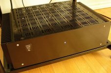
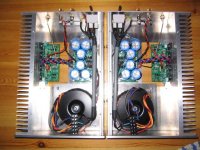
GB150 completed - front view
Listening to Jazz at the Pawnshop last night was so impressed how this amp has made my old Celestion SL6s's come alive and sound so effortless. Switched to Emma Kirkby and The Academy of Ancient Music rendering of Mozart's Exsultate Jubilate - clean, sweet, detailed, effortless Emma. All this coming out of an uncanny "black" hole silence. Still can hardly believe I'm getting this out of a diy project - not to mention the price of admission!
rez
Attachments
Has anyone experimented with different levels of output stage bias on the GB150's. I know the instructions recomment 100mA output stage current as a minimum (1V/10ohm test resistors) , but is there audible advantage in going to 150mA or 200mA with large heatsinks.
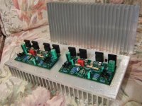
I still don't have a chassis but I have the modules built and can run them up on my bench. They were so easy to assemble, with excellent step by step instructions.
I still don't have a chassis but I have the modules built and can run them up on my bench. They were so easy to assemble, with excellent step by step instructions.
waiting for parts to arrive
Hello ska amp builders,
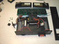
Working on my gb150d,
Have the boards together, using an B&K amp enclosure since I have it on hand.
I have ordered a 500va 35+35vac = approx. 49 vdc Avel,transformer from parts express. It was $10 more than a 330va but I thought the slightly better regulation factor of 4.3 was worth while. Have decided to go with 2- 35amp 400v diode bridges; 3-63v 6800uf 105c chemicon per side and now am looking into ps bypass caps.
Also have to tap the holes in the heatsinks-6-32.
Should be running within 2 weeks.
I am impressed by float's review of the gb150d; and what's noticed is that 37vdc rails were used...makes me wonder what effect that may have on sonics.
cheers
doggy
Hello ska amp builders,
Working on my gb150d,
Have the boards together, using an B&K amp enclosure since I have it on hand.
I have ordered a 500va 35+35vac = approx. 49 vdc Avel,transformer from parts express. It was $10 more than a 330va but I thought the slightly better regulation factor of 4.3 was worth while. Have decided to go with 2- 35amp 400v diode bridges; 3-63v 6800uf 105c chemicon per side and now am looking into ps bypass caps.
Also have to tap the holes in the heatsinks-6-32.
Should be running within 2 weeks.
I am impressed by float's review of the gb150d; and what's noticed is that 37vdc rails were used...makes me wonder what effect that may have on sonics.
cheers
doggy
Attachments
Re: waiting for parts to arrive
AFAIK the only difference you'll get from lower voltage rails is lower power and reduced dynamic headroom at a given listening level. Its a disadvantage if anything. Hence I'll be changing my trafo soon for one or two 35v units for 49/50volt rails.
This is a good question, and relevant for all builders. Why not email Greg and post his answer here?HiFiddle said:Has anyone experimented with different levels of output stage bias on the GB150's. I know the instructions recomment 100mA output stage current as a minimum (1V/10ohm test resistors) , but is there audible advantage in going to 150mA or 200mA with large heatsinks.
doggy said:
I am impressed by float's review of the gb150d; and what's noticed is that 37vdc rails were used...makes me wonder what effect that may have on sonics.
AFAIK the only difference you'll get from lower voltage rails is lower power and reduced dynamic headroom at a given listening level. Its a disadvantage if anything. Hence I'll be changing my trafo soon for one or two 35v units for 49/50volt rails.
At low voltage rail you will get a more stable amp into low impedance, that means it will be better delivering current instead of high voltage
As I recall someone has tried higher bias without any benefit.
When I adjust bias I find the value where it is most stable and it will also give optimal sound
Actually I find that is more a question about the minimal bias needed, and a few milliamps can do quite a difference, so it will be very important that left and right are alike
Make the last fine adjust one channel at a time and listen to both channels and you will hear which one is better - but it will need readjustment after some time
Question to the thread
I've read messages for 2 hours but yet to see a simple description of the size of the PCB for this amp. Can someone please tell me it width and length and height (with FETs attached)? Thanks a bunch.
Also, does anyone have a guess as to whether the heat sink in the picture below is suitable for one channel? The heat sinks are 8" X 3" X 1 3/4" and used on a 65 watt per channel Hafler 9180 amp. The main board on this amp is badly damaged so I thought to replace it with a pair of SKA amps. Any guesses?
Attachments
Thanks for the guess on the heat sinks.
Statements about the SKA being a more efficient circuit made me think smaller heat sinks might be OK.
The transformer in the picture is the International version and can be set for either around 58 ±VDC or 29 ±VDC.
This amp at this lower voltage will still play quite well, won't it?
But, what is the size of its PCB?
The GB150 is efficient with the rail voltage, considering the use of vertical mosfets.
For 50W/8 you need a bit over 1.75 Amp bias, at the exact current for 50 watts you're in the non-linear crossover zone.
Mr Ball advices less than +/-32 volts(unloaded).
I've got a heapload of dual secondary 25 Vac toroids, so i'm running it a wee higher.
For class A use Mr Ball prescribes a heatsink under 0.4 C/W, IMO that will give a very hot running amp. Lower than 0.3 C/W is much better, either a BIG heatsink or one with a vent.
Hi Dick,
those 8x3inch sinks should easily cope with a GB150 for domestic duty.
In classAB the Pq is quite low for this amp and the sink temperature will be very low (I would guess less than 6degC above ambient temperature). The sink has to dissipate about 60% of output power in addition to Pq, so for domestic duty the average power levels for conventional SPLs will be at least 20db below maximum and probably 30db below. Louder music power levels will average 10 to 20db below maximum, otherwise clipping on peak levels will occur. Peak dissipation will only happen for short period music peaks and thermal inertia of the heatsink will easily cope with this.
I would wire up one amp block to your proposed heatsink and run it pretty hard, monitoring maximum temperatures and from that information make the decision on whether one 8inch sink could cool two GB150 amps.
I suspect there is more to be gained from the SKA design.
Greg claims 20dB improvement in PSRR for his SKAs. I'd guess that this is a maximum gain over more conventional designs, and it's not clear if this applies to all frequencies. Anyway, an extra 20db PSRR doesn't mean the amp is completely insensitive to supply noise/modulation. High end amps are often regulated, providing an extra 40-80dB immunity to PS artifacts.
Therefore I think there may well be gains to be had by at decoupling the input and output stages by an RC, or possibly a cap multiplier. Going further, full regulation may be beneficial.
Comments?
I've got other stuff to do at the moment, but if/when I get round to some experiments, I'll report my findings.
GB150 monos almost ready
I finally found bit time to amp. building.
I have 4 monoblocks in progress. First pair is ready for testing. If everything goes well, i hope to get some sound from them in weekend..
Wiring is still bit messy. Transformer is quite near module.Do you think that something can be improved if i put metal box around transformer?
I made "service door" under the module, so service/tweaking is easy without need to unfasten anything.
Some minor "tweaks" are done: Trimmers are replaced to multiturn cermets, 330uf caps are bypassed with 0,1uF PP:s, some critical resistors are made from 3 paralled (2 soldered under PCB) to improve temp coefficient.
To be continue..
Attachments
Re: GB150 monos almost ready
Sounds terrific ... look forward to reading about the results
Wrsto the metal box around transformer, A farraday box/cage would be better! A way to achieve this is to use Aluminium flyscreen ... cut it and fold into a box shape around the transformer. Make sure you scrape of the protective coating on the Aluminium flyscreen when grounding it to the chasis. Also, make sure that the chassis is grounded to the earth pin of the AC connection.

Hi Pasi PPasi P said:I finally found bit time to amp. building.
Wiring is still bit messy. Transformer is quite near module.Do you think that something can be improved if i put metal box around transformer?
Sounds terrific ... look forward to reading about the results
Wrsto the metal box around transformer, A farraday box/cage would be better! A way to achieve this is to use Aluminium flyscreen ... cut it and fold into a box shape around the transformer. Make sure you scrape of the protective coating on the Aluminium flyscreen when grounding it to the chasis. Also, make sure that the chassis is grounded to the earth pin of the AC connection.
- Status
- This old topic is closed. If you want to reopen this topic, contact a moderator using the "Report Post" button.
- Home
- Amplifiers
- Solid State
- Simple Killer Amp Constructor Thread