I would like to build this.
Can we substitute a cap for the inductor resistor?
What is issue if I remove it altogether. That needs to be a BIG resistor.
Output stuff = stabilizers.
Yes, the output resistor needs at least a 5w rating. There's a cheapskate solution. Use 2 of cheap ceramic resistor. A parallel pair of cheap resistor at the output will pass signal intact. Don't forget the inductor.
") These three units all have inductance; however, since they are all in parallel, inductance decreases dramatically.
These three units all have inductance; however, since they are all in parallel, inductance decreases dramatically. The output zobel needs only a cheap 5w ceramic resistor and a cheap polyester cap. *If you make an overspend for a polypro cap, change the resistor value to within the range of 5R to 10R. And, here's why. . .
Problem: The National Semiconductor datasheet assumes mass production of television amplifiers or economy home theater units and so there wouldn't be a single piece of polypropylene accounted for. Polyester has extremely high internal resistance, ESR. This is reflected on the resistor value of the speaker output zobel in the datasheet. Using a different type of cap will remove the ESR and you must compensate the resistor value accordingly, else too much load at the output.
The LM3886 is inherently unstable and we're cutting the gain on it. In this case, I think that stability enhancement parts are required rather than optional. Fortunately, the needed parts are very economical, as well as giving us a better chance of success.
Last edited:
James,
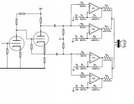
How about a SolidState Output WILLIAMSON???
Attachments
Also, when the amp runs nicely it will last longer. That's much better than sticking one of its output transistors 5 months from now and burning through our woofer. Additionally, Thiele-Small and Boucherot work together, because they're a magnitude less effective otherwise.
This link contains a great deal of blather on the topic: Embedded.com - IC Audio Power Amplifiers and Zobel Networks: One Size Does Not Fit All All of which is irrelevent because it doesn't directly relate circuit values to benefits. They've assumed that the reader will do this automatically, given the formulas that look so much like http://www.youtube.com/watch?v=rwrVcR8MZZI ; however, . . .
Your temperature probe (the one that's fastened to your heatsink) and your ears (if running the amp full band) are quite relavant.
Somewhere between technical blather and end results are the means to employ thiele-small boucherot components at the output of the amplifier. And, here's why. . .
These will help us cut the gain while keeping the amp stable. You wanted less contribution from the chipamp and more contribution from the tube, right?
Wow. These comments are so unlike me. I'll bet that AndrewT's eyebrows went up when he read all that. Normally, I'm the first to break the rules and that last to insist on them. However, I do need a chance for this project to work.
Um. . . simply put: With LM3886, try it right first and bend it later, because the other way around results in masking.
This link contains a great deal of blather on the topic: Embedded.com - IC Audio Power Amplifiers and Zobel Networks: One Size Does Not Fit All All of which is irrelevent because it doesn't directly relate circuit values to benefits. They've assumed that the reader will do this automatically, given the formulas that look so much like http://www.youtube.com/watch?v=rwrVcR8MZZI ; however, . . .
Your temperature probe (the one that's fastened to your heatsink) and your ears (if running the amp full band) are quite relavant.
Somewhere between technical blather and end results are the means to employ thiele-small boucherot components at the output of the amplifier. And, here's why. . .
These will help us cut the gain while keeping the amp stable. You wanted less contribution from the chipamp and more contribution from the tube, right?
Wow. These comments are so unlike me. I'll bet that AndrewT's eyebrows went up when he read all that.
Normally, I'm the first to break the rules and that last to insist on them. However, I do need a chance for this project to work.Um. . . simply put: With LM3886, try it right first and bend it later, because the other way around results in masking.
Last edited:
I have used a 10R 2W resistor with success. It doesn't see very much power, because it is shorted with a wire (the coil!).
The output coil seems to scare lots of people, but it is only 0.7uH (microhenry). This is almost nothing. Yet it helps a lot and doesn't do any harm at all.
A fart you can't smell, but it releaves you from a lot of inner pressure so to speak.
regards
The output coil seems to scare lots of people, but it is only 0.7uH (microhenry). This is almost nothing. Yet it helps a lot and doesn't do any harm at all.
A fart you can't smell, but it releaves you from a lot of inner pressure so to speak.
regards
Amplifier basics 101:
The output inductor//resistor isolates capacitive loads from the amplifier feedback loop. Also to isolate the internal feedback loop of the amplifier from external RF signals picked up by speaker wiring, crossover coils, driver voice coils, etc.
"Fart you can't smell...: priceless
The output inductor//resistor isolates capacitive loads from the amplifier feedback loop. Also to isolate the internal feedback loop of the amplifier from external RF signals picked up by speaker wiring, crossover coils, driver voice coils, etc.
"Fart you can't smell...: priceless
Amplifier basics 101:
The output inductor//resistor isolates capacitive loads from the amplifier feedback loop. Also to isolate the internal feedback loop of the amplifier from external RF signals picked up by speaker wiring, crossover coils, driver voice coils, etc.
"Fart you can't smell...: priceless
Hi man! Your timing is sensational. I had an accidentally to the floor chair failure.
Yes, without going off topic at all, we could indeed describe an unstable LM3886 as the electronic equivalent of cutting the cheese. You know, undesirable output?
Last edited:
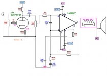
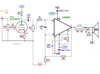
This is the schematic, with 220pF between + and - inputs (on the back of the board), 100nF between + and - rail, and 330uF on each rail (see figure 2):
Single Chip 50W Stereo Amplifier
The layout is here:
http://www.diyaudio.com/forums/chip-amps/126904-lm3886-noise-issue-2.html#post1570826
The whole amp looks like this:
http://i36.tinypic.com/oixjtg.jpg
http://i37.tinypic.com/2e2owlc.jpg
http://i34.tinypic.com/2ihnupf.jpg
http://i34.tinypic.com/ny7h1j.jpg
the 2u2F and 10k pot define the high pass of the power amp.
The 4uF+4k75 MUST be larger to match the 2u2F. Try >=6u8F
The +IN pin sees DC resistance of 1K to 11k. The -IN pin sees 56k2. This will increase the output offset.
The +IN pin sees impedance vary from 1k to 3k5. With 220pF RF filter this is just about OK, but may need some adjustment.The RC in the NFB may not be required. Leave space just in case.
I recommend you keep the R//L in the output lead. 0.7uH and between 1r to 10r would work.
The 220pF RF filter does not need to be 1%. 5% or 10% or 20% is good enough.
Pin8 must not connect to signal ground. Connect pin8 to PG. A fixed resistor will give near instant turn on. Look at National for delayed de-mute. It only needs a few tens of ms.
You have almost 40dB of total gain and using two pots to reduce this. I fear that noise will be a problem.
Most Power amps make do with between 26dB and 30dB of gain with one volume pot back at the pre-amp/source.
Last edited:
the 2u2F and 10k pot define the high pass of the power amp.
The 4uF+4k75 MUST be larger to match the 2u2F. Try >=6u8F
The +IN pin sees DC resistance of 1K to 11k. The -IN pin sees 56k2. This will increase the output offset.
The +IN pin sees impedance vary from 1k to 3k5. With 220pF RF filter this is just about OK, but may need some adjustment.The RC in the NFB may not be required. Leave space just in case.
I recommend you keep the R//L in the output lead. 0.7uH and between 1r to 10r would work.
The 220pF RF filter does not need to be 1%. 5% or 10% or 20% is good enough.
Pin8 must not connect to signal ground. Connect pin8 to PG. A fixed resistor will give near instant turn on. Look at National for delayed de-mute. It only needs a few tens of ms.
You have almost 40dB of total gain and using two pots to reduce this. I fear that noise will be a problem.
Most Power amps make do with between 26dB and 30dB of gain with one volume pot back at the pre-amp/source.
Andrew,
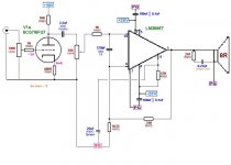
I have revised the schematic after doing research on other Gainclone type chip amps.
I have seen many that are just 3 resistors and have NO problems with RF or HF noise. Now I think that the "noise floor" is a subjective thing and rather than just go along with what others are doing I want to include some of the "tips & tricks" that avoid it.
I put the inductor and resistor back in along with a Zobel to be directly at the speaker connections. I plan for the wiring to the subwoofers to be no more that 1.5 meters of good quality O2 free copper, large guage.
I plan to build the subwoofer enclosures myself with particular attention to the quality (ie flatness of impedance curve) of the woofer/enclosure for the desired frequency response.
The listening room I am building in my basement will contain NO Florescant lighting and the power lines will be well designed and filtered.
Attached is what I have come up with as a "semi final" design. The questions I have are as follows.
1: The 220pF filter is it needed and if so is 220pF a correct value? I like to avoid as many caps in my designs as possible.
2: Can the gain of the chip amp be reduced further?
3: I could not find any confirmation that a cap is needed on Ri so according to my preference I removed it.
4: Aside from the difficulty in actual layout/soldering is there any disadvantage to Point to Point wiring? If so can you recommend a "kit" PCB?
Some further details of the system in which this is to be implemented.
The sources as I intend them to be are as follows:
PC Audio (FLAC,MP3, etc) from a Firewire Interface (M-Audio, Behringer TBD)
BIC Turntable with Shure Cartridge and 6SL7 Tube Preamp w/passive RIAA
Vintage "New Englander" AM/FM Tuner
Occasional Cassette
Source Selector/Preamp/100hz L/W TUBE crossover (Designed by myself)
The Sub out will go directly to this "Hybrid" amp
The High Pass will then go to
2nd TUBE crossover 18db/Octave (designed by Pete Millett)
Highs - 30W/CH Push Pull 1625 (military 807's) Triode mode Amp (my design)
Mids to 25W/Ch Push Pull 829B Amp Triode Strapped in Parallel (my design)
The final drivers have not been determined at this point, these are my future adventures to learn about enclosure designs other than sealed and vented.
Do not worry about the power output of the tube amps. They will operate at less than half of their rated power to avoid excessive distortion.
As you can see there is already an excessive number of capacitors and resistors in the signal path from source to speaker. I want to keep as many more out of the path as possible.
Attachments
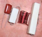
Yes, the gain can be reduced to somewhere between 10 and 18. I'm still collecting samples to try out and find the best. The weekend is coming in just 4 hours. I did find a more seemly size output resistor. The zobel remains with the 5w for longevity. The best of the trials (now 7 Lm3886's available for that) will need to run in overnight and be re-evaluated. This pretty thing just came in the mail:
Attachments
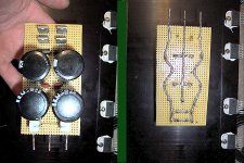
Lofty goals indeed. So far, I got the power supply built and four of lm3886 stuck to a significant heatsink. These old model LM3886T's were junk box parts. Please don't hotsink like this--use the safer LM3886TF (insulated version) instead. The thermal interface of LM3886TF can work fantastically well with Arctic Silver compound. . . altogether more seemly, but not $free like this was.
For the sturdy Stancor 20-0-20, 4 amper, EI core transformer pictured earier, this power supply is a center tap version of the CarlosFM 2004. The 16ga cable is thickly soldered all the way through to the inside of the cable. Contacts of the MUR860's pierce the centerpoint of the cable before it was soldered. After the [forgotten] transformer taps are added on, the diodes should be sufficiently heatsinked.
It appears to be very low inductance and it should be able to take quite the beating from the woofer amp. This design is supposed to help for dynamic, live sound, bass. We'll find out.
Attachments
Last edited:
- Status
- This old topic is closed. If you want to reopen this topic, contact a moderator using the "Report Post" button.
- Home
- Amplifiers
- Chip Amps
- Simple Chip Amp for P to P wiring