Broskie goes on in the article to explain that he would not build that circuit. He is worried that the chips arent up to the task.
I think this is because of the High voltage supply. Another reason I would separate the tube supply, this way a much lower voltage ie 30V or so can be supplied to the chips. Heat dissipation is lowered and I think the chips can hadle it then.
He also states that an output Zobel is needed and I am sure I will need to consult the data sheet to see what National suggests for parallel operation. Can anyone offer suggestions as to that is the 10R 0.7uH OK?
coldcathode, you better stick to your initial design. You have a minimum of components and 95% to make sound good from the first try
I don't see the point to complicate the things unnecessary. Either common cathode or SRPP will be excellent.
Ratza,
I think you are correct, I will look at doing a more complicated circuit in the future after getting this one "under my belt".
Since the supply voltages are the same in both designs, I can easily just purchase larger than needed transformers. If I feel the need for "more power" I can go that route in the future.
How about the idea of two potentiometers.
The theory was that I could use them to match up the signal levels as needed.
When I used to build Car Stereo systems in my younger days we would start with the source "turned up to 11" and turn up the gains until just about clipping. Then we knew that unless you cranked the source all the way up you would get almost peak power without clipping.
I am looking at it the same way, put in the highest level of source with a "mid" amount of source to the chip. Turn up the tube until it sounds crappy then back of just a bit. Then turn up the chip till it starts to clip and back off.
This way the overall gain becomes "ideal" and the master volume control has full range without overdriving the system.
in the inverting amplifier, the Negative FeedBack components determine the input impedance.Why not?
In the non-inverting amplifier, the NFB components do not determine the input impedance. The intrinsic impedance of the +IN is the raw input impedance and this is paralleled with any parasitics and additional Rin components.
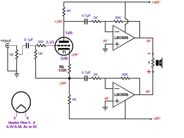
that bridged circuit may destroy your 3886 amps.A bigshout out to Jpeitzman for the link. !!!!!!!!!!!!!!!!http://www.diyaudio.com/forums/atta...6738t-simple-chip-amp-p-p-wiring-hyrbidpp.jpg
I see +-40Vdc (+-variations due to mains supply) and an 8r0 load.
Each 3886 is effectively driving a 4ohm speaker load from the +-40Vdc supply. This will overheat the chips.
Look at the page 14 graph. The heatsink data is off the top of the graph/table for both 4r0 and 6r0 loading.
Depending on how stiff the 40V supply rails are the power graph predicts between 70W and 82W into 8r0.
I would expect a 4r0 load to attempt to draw something approaching 140W before the chips cut off.
The bridged output will try to approach 280W into 8r0 if the input voltage is set appropriately.
Last edited:
that bridged circuit may destroy your 3886 amps.
I see +-40Vdc (+-variations due to mains supply) and an 8r0 load.
Each 3886 is effectively driving a 4ohm speaker load from the +-40Vdc supply. This will overheat the chips.
Look at the page 14 graph. The heatsink data is off the top of the graph/table for both 4r0 and 6r0 loading.
Depending on how stiff the 40V supply rails are the power graph predicts between 70W and 82W into 8r0.
I would expect a 4r0 load to attempt to draw something approaching 140W before the chips cut off.
The bridged output will try to approach 280W into 8r0 if the input voltage is set appropriately.
Andrew,
I noticed that myself when I looked at the National Paper on bridging. The Supply would need to be lowered to like +/- 20V for 4 ohms.
I am not sure I need all that power or heat.
On another topic,
The data sheetfor the LM3886 has a convoluted equation for the roll off frequency created by Rf2 and Cf. It has a variable of "s" I can't find the definition of that variable?
Questions
1: Do I need this circuit assuming the input is only Low frequencies?
2: If I do need it then how to calculate values.
Rf1 will be 56K
Yep, it would be nice to have a "distortion" maker in the circuit. So the idea with two pots is good.
My brother in law is a Ghee-Tar player. I am thinking that a bridged setup of two 3886's driven by a 12AX7 Long Tailed Pair into a 16ohm Guitar speaker would be pretty cool!!
Broskie does have a similar design that uses an LM12 (obsolete) in a similar circuit where the tube is enveloped in the feedback network, therefore calling all the shots. ...digging...
index
It is about three fourths of the way down the page. The Broskie articles contain ideas I have kicked around, but that is as far as I have gotten. I built a couple of chip amps at the very beginning then went to tubes with a slight diversion into simple sand, haven't done much with them since. Sorry I didn't chime in earlier with the articles, I don't always frequent this section like I do the others.
BTW, IF...big if... you give more thought to the push pull idea Nelson Pass has some posts scattered around somewhere about a super-symmetric chip amp. I have a feeling that a SuSy LM3875 with a JFET front end may sound quite...zenful

James
index
It is about three fourths of the way down the page. The Broskie articles contain ideas I have kicked around, but that is as far as I have gotten. I built a couple of chip amps at the very beginning then went to tubes with a slight diversion into simple sand, haven't done much with them since. Sorry I didn't chime in earlier with the articles, I don't always frequent this section like I do the others.
BTW, IF...big if... you give more thought to the push pull idea Nelson Pass has some posts scattered around somewhere about a super-symmetric chip amp. I have a feeling that a SuSy LM3875 with a JFET front end may sound quite...zenful
James
BTW, IF...big if... you give more thought to the push pull idea Nelson Pass has some posts scattered around somewhere about a super-symmetric chip amp. I have a feeling that a SuSy LM3875 with a JFET front end may sound quite...zenful
James
James,
I assume the ZEN pun was intended
I don't know anything about the consensus, but I doubt that those differences in phase margin cause overshoot in audio signals.I take it that your comment means you are not one of the consensus.
Or are you saying that I made up the Member's opinion?
I built a LM3886 based amp with gain of 10 (marginally stable->your words!) almost 13 years ago and it didn't showed any signs of instability or overshoot.
Regards
indeedI assume the ZEN pun was intended
Here is some food for thought on that subject.
James
Attachments

in the inverting amplifier, the Negative FeedBack components determine the input impedance.
In the non-inverting amplifier, the NFB components do not determine the input impedance. The intrinsic impedance of the +IN is the raw input impedance and this is paralleled with any parasitics and additional Rin components.
I know that. Haven't I dait it a few posts behind? Anyway, right now I think I had a drink more than I should've had. I will probably (read surely) regret it tommorow.
Hey guys. Let's not bridge the LM3886--I can heatsink almost anything for you, but I'd rather not do it that way. You could use it instead of the fireplace. The heatsinks are about $50 for the pair. And the sound will be sickening at best. Please don't increase noise--it has enough already. Please use parallel or solo instead.
Last edited:
I don't know anything about the consensus, but I doubt that those differences in phase margin cause overshoot in audio signals.
I built a LM3886 based amp with gain of 10 (marginally stable->your words!) almost 13 years ago and it didn't showed any signs of instability or overshoot.
Regards
Good news! I've found 5 of LM3886 available for live test.
I'd like to do a gain 10 inverting LM3886 to start out with. Any clues on resistor values? Or, shall I simply guess five times and pick the one that works best?

Heres what I have come up with.
Questions in Pink Boxes . . .
Woah!! far too much load at the output. Please specify the zobel cap as polyester (not polypro).
Yes, we do need the output inductor//resistor. Its necessary for stability.
Your DC voltage is approximately 30+30 although it may be 29+29.
The RC parallel to the feedback resistor is probably unnecessary if the feedback resistor is metal film.
It may be tough to source 39uF caps--can we use common values?
Last edited:

coldcathode, don't tie the 'tubes ground' to the mute input, can't be good
Regards
Juergen Thanks for the CATCH! I would not have wired it that way but I have fixed the schematic.
Daniel,
What do you mean load at the output?
- Status
- This old topic is closed. If you want to reopen this topic, contact a moderator using the "Report Post" button.
- Home
- Amplifiers
- Chip Amps
- Simple Chip Amp for P to P wiring