The sphincter comment was made purely in jest. The implication was that MY opinion is like any other. There is a difference between FACT and Opinion. The specific characteristics of the chip amp are FACT, the subjective reasons why I want to drive it with a tube are mostly OPINION.
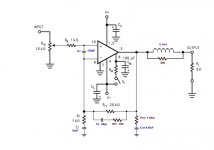
Any way here is what I have come up with,
I intend to power it with 200VA Antek 22V torroids. One torroid for each channel. Once I have it running in a way that I like I will probably also power the tube with a torroid for symmetry on chassis.
Where to buy the .7mH inductor or can it be made with a few turns of wire over the resistor?
Attachments
With plentiful science to back that up, if necessary. In cause and effect, there's no end of measurable reasons why you like the tube amp. As for me, I'd like to try it because professional musicians and arena concert DJ's use tubes. That's an observation, not an opinion. I'm curious if I hear what they hear.. . . the subjective reasons why I want to drive it with a tube are mostly OPINION.
This experiment will have fierce competition in the form of LM1875 on regs as a comparison point. If the tube wins the competition, that will be significant indeed.
All of this is probably "branding the sound" in a way; but, individual rooms do ever so much more harm to the signal that, for me, the distortion factor is utterly moot. I don't have a padded chamber and I dislike the equalizer.
") My speakers are built suit individual rooms. Therefore, both cancellations and peaks are potentially useful as long as it sounds clear. Such is the way of an active speaker.
My speakers are built suit individual rooms. Therefore, both cancellations and peaks are potentially useful as long as it sounds clear. Such is the way of an active speaker. For me, the equalizer is a "one fell swoop" approach that is heavy-handed so that the audio may sound fake. Instead, of one large effect, many small voicings can work better--Attention to clarity every time makes it work. I think that this is a definitive difference between mid-fi and hi-fi markets.
Any way here is what I have come up with,
I intend to power it with 200VA Antek 22V torroids. One torroid for each channel. Once I have it running in a way that I like I will probably also power the tube with a torroid for symmetry on chassis.
The torroid is probably a good choice. It seems that you have inbuilt some amount of tolerance for 4 ohm speakers, considering that 22vac voltage, per each bridge rectifier, per each rail.
As for me, I'm testing out the Stancor 160va 20-0-20 (20 center tap makes almost same voltage as 22 dual) and a pair of 24-0 to see which is more pleasant.
Power supply is so much like a woofer crossover that I'm sure we could get similar results with different transformers or different results even if we did buy exactly the same transformer.
To answer a previous question: If you wish a full bandwidth LM3886, please do parallel LM3886 to reduce distortion via cancellation on noise. Otherwise, I wouldn't be able to follow the project because my ears cannot withstand a full audio band LM3886 unless it is parallel. Its that parallel is the most appropriate choice that I can make on the "sound of" LM3886 and without parallel operation, my options become insufficient/inappropriate. Sorry about that.
Where to buy the .7mH inductor or can it be made with a few turns of wire over the resistor?
Turns of wire over a round resistor works well. Um? Can we use a 4 ohm resistor? Personally, I have better luck with that.
Last edited:
. . .Any way here is what I have come up with,. . .
Nice!
And I will go find the heatsinks, the LM3886's and supplies and give it a test drive. Also, please specify the output zobel capacitor as polyester. National Semiconductor forgot to mention that on the datasheet.
Last edited:
Hybrid GainClone Amplifiers
New Hybrid SE OTL? & Aikido Gainclone & Circlotron Lie Detector
If anyone here is still talking about a tube fronted chip amp, have these been read? They may be of interest to some if you haven't seen them.
New Hybrid SE OTL? & Aikido Gainclone & Circlotron Lie Detector
If anyone here is still talking about a tube fronted chip amp, have these been read? They may be of interest to some if you haven't seen them.
coldcathode said:Where to buy the .7mH inductor or can it be made with a few turns of wire over the resistor?
10 turns of enamelled 18 or 20AWG copper over the body of a 10 ohm / 3W resistor.
You can see oscillations if you have an oscilloscope, they're not in the audio band. The chip will heat like crazy anyway. Build an inverting and a noninverting circuit, both with a gain of 2. Resistor values for the noninverting configuration should be 10k for all. For the inverting configuration only the feedback resistor changes to 20k. The input impedance will be 10k for both variants.danielwritesbac said:How to apply it?
I can heat up the soldering irons pretty quickly and give it a try (if I knew what it was that I was trying).
It is true that tubes sound different, but it depends alot on what configuration you use. The buffer I made with E88CC (Tesla) is extremely neutral, if you don't see the active device you don't know what's inside the circuit. If I make an anode amplifier or a SRPP, you'll know for sure that there is a tube somewhere
Last edited:
10 turns of enamelled 18 or 20AWG copper over the body of a 10 ohm / 3W resistor.
You can see oscillations if you have an oscilloscope, they're not in the audio band. The chip will heat like crazy anyway. Build an inverting and a noninverting circuit, both with a gain of 2. Resistor values for the noninverting configuration should be 10k for all. For the inverting configuration only the feedback resistor changes to 20k. The input impedance will be 10k for both variants.
It is true that tubes sound different, but it depends alot on what configuration you use. The buffer I made with E88CC (Tesla) is extremely neutral, if you don't see the active device you don't know what's inside the circuit. If I make an anode amplifier or a SRPP, you'll know for sure that there is a tube somewhere
Yes, how to get unstuck? The LM3886 starts acting nearly appropriate at about gain 29 (centerpoint)--like its "stuck" on that figure or a similar figure.
I think that for this project, the tube has to control the negative feedback so it can tell the lm3886 "don't do that" which is what negative feedback does anyway, isn't it?.
Last edited:
You mean how to read out the diagram?
I was just thinking of something: if the level at the LM input is too high, you can use a voltage divider after the anode capacitor. I know it doesn't make too much sense, but all you both want is the tube timbre. In this way the low frequency response will be improved and the tube will see a higher impedance at the output. The system could be something like this: tube --> attenuator --> chip (let's say 24dB gain --> -24dB attenuation --> 30dB gain)
I was just thinking of something: if the level at the LM input is too high, you can use a voltage divider after the anode capacitor. I know it doesn't make too much sense, but all you both want is the tube timbre. In this way the low frequency response will be improved and the tube will see a higher impedance at the output. The system could be something like this: tube --> attenuator --> chip (let's say 24dB gain --> -24dB attenuation --> 30dB gain)
We could, you know, give the tube a really tall order, as in how to drive a 70w power amp to its full potential when that power amp has a 120k input load. That'll throw away power like its gone out of style. Possible fix for the "too much gain" situation? Or, is it inappropriate?
Hi Ratza! We posted at almost the same time on almost the same idea. Oh my!
Hi Ratza! We posted at almost the same time on almost the same idea. Oh my!
Last edited:
Input impedance of the amplifier has nothing to do with the output power. Normally it's good to have the input impedance as high as possible to be easy to connect with any preamplifier, tuner, tape etc. There is a downside of a high impedance, and that is that the circuit will be more sensitive to parasits.
Now back (well... forward) to output. The biggest power transfer is when the output impedance of the amplifier is exactly the same with the load impedance. The biggest voltage transfer is at infinite load impedance. It's very easy to demonstrate this, you only need to apply Ohm's law.
Now back (well... forward
) to output. The biggest power transfer is when the output impedance of the amplifier is exactly the same with the load impedance. The biggest voltage transfer is at infinite load impedance. It's very easy to demonstrate this, you only need to apply Ohm's law.Input impedance of the amplifier has nothing to do with the output power. Normally it's good to have the input impedance as high as possible to be easy to connect with any preamplifier, tuner, tape etc. There is a downside of a high impedance, and that is that the circuit will be more sensitive to parasits.
Now back (well... forward
Yes, I meant the output power of the preamp.
The role of an active preamp is to adapt impedances and eventualy correct volume, ballance and tone of the signal. The power of the preamplifier isn't that important. What is really important is the output impedance and output voltage. You are sending only the voltage further to the power amplifier, the current isn't that important, unless you use a low input impedance amp.
I think you make a confusion between the output impedance of an active device and the impedance of the load. There are two very different things. Look at the following image:

The output impedance is RS and the load impedance is RL. In practice they are anything but purely resistive, introducing signal distorsion in amplitude, shape, phase and so on. Now, if your preamp has output impedance of 10k, it doesn't mean that you really need to match it with the power amp input. I can explain further on how the things work, but it's better for you to take a look on the wikipedia articles related to opamps, impedance and so on. They are very well explained, even a person who never heard of electronics should cope with them.
As you see, analog signal engineers are havin tons of challanges. You cannot imagine how the things are in RF.
I think you make a confusion between the output impedance of an active device and the impedance of the load. There are two very different things. Look at the following image:
The output impedance is RS and the load impedance is RL. In practice they are anything but purely resistive, introducing signal distorsion in amplitude, shape, phase and so on. Now, if your preamp has output impedance of 10k, it doesn't mean that you really need to match it with the power amp input. I can explain further on how the things work, but it's better for you to take a look on the wikipedia articles related to opamps, impedance and so on. They are very well explained, even a person who never heard of electronics should cope with them.
As you see, analog signal engineers are havin tons of challanges. You cannot imagine how the things are in RF.
The role of an active preamp is to adapt impedances and eventualy correct volume, ballance and tone of the signal. The power of the preamplifier isn't that important. What is really important is the output impedance and output voltage. You are sending only the voltage further to the power amplifier, the current isn't that important, unless you use a low input impedance amp.
I think you make a confusion between the output impedance of an active device and the impedance of the load. There are two very different things. Look at the following image:
The output impedance is RS and the load impedance is RL. In practice they are anything but purely resistive, introducing signal distorsion in amplitude, shape, phase and so on. Now, if your preamp has output impedance of 10k, it doesn't mean that you really need to match it with the power amp input. I can explain further on how the things work, but it's better for you to take a look on the wikipedia articles related to opamps, impedance and so on. They are very well explained, even a person who never heard of electronics should cope with them.
As you see, analog signal engineers are havin tons of challanges. You cannot imagine how the things are in RF.
Oh, absolutely right. Yes, I did assume that it was quite like the difference between 2 ohm and 32 ohm speakers.
P.S. I did build an FM radio from scratch. That was quite frustrating with the darned coil.
I take it that your comment means you are not one of the consensus.Andrew, I doubt this!
Regards
Or are you saying that I made up the Member's opinion?
10 to 12 turns of approx 6mm diameter using 0.8mm or 1mm diameter enameled copper wire.Where to buy the .7mH inductor or can it be made with a few turns of wire over the resistor?
why should Rin of both variants be the same?Build an inverting and a noninverting circuit, both with a gain of 2. Resistor values for the noninverting configuration should be 10k for all. For the inverting configuration only the feedback resistor changes to 20k. The input impedance will be 10k for both variants.
For the input stage I am thinking that we need attentuation on both sides of the tube.
Similar to a Guitar amp that has a GAIN control and a Volume control.
In effect what we would be doing is assuring that we can keep both the tube and the chip at signal levels they both "like".
My only concerns with the tube input are the need for the coupling caps which will introduce there own time constants into the signal. I try to avoid as many coupling caps as possible in my tube am designs. We also need to avoid STACKING any of the F3 points in the circuit.
The idea of a voltage divider network is great and in essence a Potentiometer would be an adjustable voltage divider. So if we keep the circuit as I drew with a gain of 20 is that ok?
I am thinking maybe we need to increase Rin to a 100K potentiometer. Also, maybe decrease the gain to about 15. I will work that out and include a tube driver circuit for the 100K input load.
Hybrid GainClone Amplifiers
New Hybrid SE OTL? & Aikido Gainclone & Circlotron Lie Detector
If anyone here is still talking about a tube fronted chip amp, have these been read? They may be of interest to some if you haven't seen them.
Thanks!!
I had not read the Broskie article because I do not build Aikido amps. The info is very good though and I think we can achieve satisfactory results going down the path we have chosen.
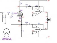
The "Push Pull" circuit with the split load tube and parallel chips seems very intriguing!!!!
Daniel,
You have the components needed for this, Rk is 120Ohm for the 6922.
This configuration will not have all the gain you need. We can add another tube gain stage in front of it, OR we can increase the gain on the chips. Broskie is only running the gain @ 15. I am sure we can increase this but the chip guys need to confirm.
I REALLY Like this and feel that I will probably go this route. I wish I had read all of the GlassWare articles prior to starting this thread or maybe JPeitzman might have tuned in earlier.
I had the idea of a "Push Pull" amp in the back of my mind for sometime. Push Pull Triodes give excellent power and VERY reduced Distortion on the even order harmonics. Bear in mind a couple things. MATCHING the gains on both chips will be important. You will need to hand match some very low tolerance resistors in the feedback path. The output taken from the plate of the tube is INVERTED copy of the signal. At the cathode the signal is IN PHASE with the input. In effect we are building a Class A push pull amplifier.
What is nice is any nonlinearity in the tubes response cancels out.
Since I expect to be driving my amp with about 2VRMS signal this circuit will work perfectly. In the case of low input signal we can simply add another Gain stage with another triode.
There is also no reason why we can't run the tube from a separate supply voltage. The tube is only AC coupled to the chips via the 4.7uf caps.
The reason I say this is the sound of the tube will be determined by the regulation in the powersupply to the chips in this design. So any variation in the voltages presented by the Power Supply changes the Operating Point of the tube. I also do not like Broskies math. He shows that there is 8mA thru Rk and 5mA thru each 4K load resisitor. I have no idea where that other current comes and goes. It is probably just his "rounding" but I would rather recalc my own operating point and use a separate supply.
We will need 6.3V 0.3A supply for the tube heater so a small transformer for B+ a Tube Rectifier and filament supply is no big deal.
Daniel,
If you do not mind being a "Guinea Pig" can you try this circuit as I drew it?
I am interested in the grounding scheme. I assume we "float" the speaker since it is returning to ground alternately thru the chips.
A big
 shout out to Jpeitzman for the link. !!!!!!!!!!!!!!!!
Attachments
- Status
- This old topic is closed. If you want to reopen this topic, contact a moderator using the "Report Post" button.
- Home
- Amplifiers
- Chip Amps
- Simple Chip Amp for P to P wiring