If you read the link I posted earlier, I show how cascaded 1st-order filters can still sum 'transient perfect' if you do it right. Each driver has a response that rolls off somewhere between 1st order and 4th order. The acoustic rolloff starts 1st order and gets steeper later.I'd like to see some evidence. You can say its a gimmick and they can refute it and theres no conclusion without evidence.
HTGuide Forum - Duelund meets Dunlavy (aka Duelund meets transient perfect)
Are you sure?
What?? Why would I plot a logarithmic speaker and acoustic phase response on a linear scale? I thought linear and coherent were the same thing when it came to phase. Being that speakers are logarithmic in nature, there is no reason to graph on a linear scale.
Later,
Wolf
Are you sure your own design is linear phase? Note that linear phase means linear when plotted on a linear frequency axis, not log.
What?? Why would I plot a logarithmic speaker and acoustic phase response on a linear scale? I thought linear and coherent were the same thing when it came to phase. Being that speakers are logarithmic in nature, there is no reason to graph on a linear scale.
Later,
Wolf
They are not the same, a linear phase system exhibits a pure time delay, with zero phase shift apart from that due to the delay itself so phase(f) = 2*PI*f*delay (radians), the linear relationship between frequency and phase is where the term comes from.I thought linear and coherent were the same thing when it came to phase.
What?? Why would I plot a logarithmic speaker and acoustic phase response on a linear scale? I thought linear and coherent were the same thing when it came to phase. Being that speakers are logarithmic in nature, there is no reason to graph on a linear scale.
Later,
Wolf
It is true that for most things acoustic that logarthmic scales are more appropriate. But when it comes to linear phase that is only a valid notion for linear frequency scales. What we are really striving for is constant group delay: all frequencies through the system having the same delay and waveforms are therefore undistorted. Delay time = -dphi/domega or the minus slope of the phase curve. So if a phase curve drops 60 degrees in 1000 cycles that would represent a certain delay. With log scales, at high frequencies where the scale scrunches together that would appear to be a steeper curve for the same calculated delay.
Coherence? Not really sure what that means.
David
Coherence? Not really sure what that means.
Hello Speaker dave
Glad I am not the only one who was wondering what it meant.
Rob
")
Probably it is an extension of the term coherent ,that, when executed well ,and it happens only with tweeter coaxial with the woofer , the two sources resembles a point source loudspeaker response .Hello Speaker dave
Glad I am not the only one who was wondering what it meant.
Rob
OK so where does a Urie 811C fall is it coincident, coherent or both?
Rob
Coaxial?
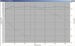
It's funny how looking at the same thing in a different way can give a completely different perception. To my untrained eyes, looking at my speakers response with a linear X axis looks much better (especially when limiting the freq to 13K...
I tried it because of the comments about linear phase, and whilst I don't think that my speaker is exhibiting linear phase (if I understand properly what that means) it gives me a different view of things.
Can anyone post a plot of a speaker that does exhibit linear phase so I can compare
The plot below is from 100Hz to 13Khz and was measured using holmimpulse. I limited to this freq range mainly to get more "room" at the lower frequencies, but also because it looks more impressive without the droop that starts at about 14K since I can't hear past 13K anyway for me it is fine...
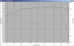
The second plot is the same response plotted with a normal log X axis.
What I'm wondering is whether the difference in slope for the mid-bass vs the tweeter is driver or crossover dependent, ie is driver selection the critical thing, or the crossover design? I'm leaning towards crossover since the sim for a 4th order shows the slope being steeper for the mid-bass unit.
I don't have access at the moment to the original measurement, so can't say what the gating was, but suspect that around 300Hz was the lower limit.
Tony.
(especially when limiting the freq to 13K... I tried it because of the comments about linear phase, and whilst I don't think that my speaker is exhibiting linear phase (if I understand properly what that means) it gives me a different view of things.
Can anyone post a plot of a speaker that does exhibit linear phase so I can compare
The plot below is from 100Hz to 13Khz and was measured using holmimpulse. I limited to this freq range mainly to get more "room" at the lower frequencies, but also because it looks more impressive without the droop that starts at about 14K
since I can't hear past 13K anyway for me it is fine... The second plot is the same response plotted with a normal log X axis.
What I'm wondering is whether the difference in slope for the mid-bass vs the tweeter is driver or crossover dependent, ie is driver selection the critical thing, or the crossover design? I'm leaning towards crossover since the sim for a 4th order shows the slope being steeper for the mid-bass unit.
I don't have access at the moment to the original measurement, so can't say what the gating was, but suspect that around 300Hz was the lower limit.
Tony.
Attachments
Probably more driver dependent.
In general terms you will see an average slope over the woofer region and average slope over the tweeter region (if a 2-way) and those slopes are proportional to unit delay and dominated by the driver's physical depth. Crossovers, if well done, will give a smooth link between the units and likewise a smooth phase transtion. With higher order crossovers, though, you will often have an 180 degree + phase transition to give best response.
David
If you read the link I posted earlier, I show how cascaded 1st-order filters can still sum 'transient perfect' if you do it right. Each driver has a response that rolls off somewhere between 1st order and 4th order. The acoustic rolloff starts 1st order and gets steeper later.
Hi Catapult,
I just went back and studied your simulation. This is very interesting and truly is a linear phase multiway with higher order. (Didn't make sense until I figured out it was a 5-way.)
The referenced thread points out the pluses and minuses, but I do believe that the power handling would be better than all first order. Units would have to be physically time alligned (stepped baffle) and the response can't be filters only, but must be filters plus drivers. Still, the out-of-band extra poles lets you deal with each driver's inherent roll-off, a problem that Thiel has to struggle with, with first order only acoustic targets.
Also agree with a symmetrical layout. I remember the B&O which we always thought of "as a one dimensional solution to a three dimensional problem". Linear phase with crappy off axis response is a very poor compromise.
David Smith
Hi Dennis, I'm assuming that your stacked first orders would have to be active? I'm having trouble with the concept of stacked first order passive filters, as wouldn't that for instance for the tweeter just be a number caps in series, ending up with the equivalent of a smaller single cap?
Tony.
Tony.
Hi Tony,
It would be just like any passive crossover design except the acoustic target curve is different. First pole is a series cap, second pole is a shunt coil, etc. You'd need good measurements of the drivers and some good software like LspCAD or SoundEasy to pull it off. Even then, it would definitely be a challenging design -- good for someone who is bored with how easy passive 3-ways are.
It would be just like any passive crossover design except the acoustic target curve is different. First pole is a series cap, second pole is a shunt coil, etc. You'd need good measurements of the drivers and some good software like LspCAD or SoundEasy to pull it off. Even then, it would definitely be a challenging design -- good for someone who is bored with how easy passive 3-ways are.
Yes, it could be an LC ladder network as long as the values are chosen to keep it as multiple sections with a Q of 0.5 (first order). Alternatively it could be C, R (to ground), C, R (to ground) etc. The R terminations of each section make them independent 1st orders rather than a number of capacitors in series.
Don't forget that the targets shown (the cascaded 1st orders with sequential cutoffs) needs to be the response of the network plus the drivers. The drivers will roll off at least 2nd order so they will use up 2 orders of the total (probably 2 orders each side). Also, since their rolloffs won't exactly match the model, some EQ will be needed to get the right total response. Usually an optimizer program fitting to the targets will get you there if it is at all possible.
David Smith
Last edited:
- Status
- This old topic is closed. If you want to reopen this topic, contact a moderator using the "Report Post" button.
- Home
- Loudspeakers
- Multi-Way
- significance of phase