The jitter may be far less important in this case. They are sampling 64 times per cycle. They are averaging in a way that reduces noise (jitter) and as long as the signal remains pretty constant the averages of its level at the sample point will converge on the signal and the noise will gradually evaporate.
I think the above means they are taking 16 moving averages.
(pg 34 of the scanned manual)625 Arithmetic Logic Circuit (A13-QA3, QAS, QA6, Q10 1
QA]. 2 , QAI 3 , QA1 5 , QA1 6 , QA 2 1 , QA 2 3 , QA 2 4 , QA 2 6)
This circuit reduces the components (hum, noise) nonsynchronized
to the fundamental frequency.
If the A/D converter output is EIN and the memory content
is Em, then the following arithmetic operation is conducted:
(EIN- EM)/16 + EM = EM
I think the above means they are taking 16 moving averages.
The jitter may be far less important in this case. They are sampling 64 times per cycle. They are averaging in a way that reduces noise (jitter) and as long as the signal remains pretty constant the averages of its level at the sample point will converge on the signal and the noise will gradually evaporate.
(pg 34 of the scanned manual)
I think the above means they are taking 16 moving averages.
I don't understand this formula. How it outputs a nominal level signal.
The formula given in the patent makes more sense. (1+k)/(1-K) or
sample value(1+k) / sample value(1+k) always results in a unity output.
The description in the text gives yet another formula of Ein(1-K) + (Em*k) -> Em
where k is 0<k<1. This also results in a unity output.
If k = 0.25 then Ein(0.75) + Em(0.25) = 1
I don't know if we can find anything more complex than the Shibasoku AG725 being built almost entirely from discrete logic components and analog IC's.
This all out assault by ShibaSoku's method/technique on accurately measuring harmonics seems to get picked up by other Japanese harmonic test equipment brands with added features and newer IC's etc; Such as, Panasonic, National and similar brands... I have some manuals from those coming to see/compare.
-RNM
Last edited:
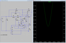
Shibasoku A3 simulation
I tried simulating the A3 notch filter (attached) in LTspice IV but with the values from the manual I only get about a 3 dB notch. I'm clearly missing something. If I change R29 (R6 in the sim) up by a factor of 10 it gets a 40+ dB notch. But all the drawings in the manual and Pchi's drawings indicate that the 3K ohm range is right. What have I missed? I did not include the shield driver since the sim doesn't have relays or stray capacitance. I did include the cap null for the opamp.
I tried simulating the A3 notch filter (attached) in LTspice IV but with the values from the manual I only get about a 3 dB notch. I'm clearly missing something. If I change R29 (R6 in the sim) up by a factor of 10 it gets a 40+ dB notch. But all the drawings in the manual and Pchi's drawings indicate that the 3K ohm range is right. What have I missed? I did not include the shield driver since the sim doesn't have relays or stray capacitance. I did include the cap null for the opamp.
Attachments
Thanks for the tip. The caps seem to have a ratio of 10:1. I am guessing since its not really specified but that works with values from the board. I revised the simulation. i revised it and tuned it to 1 KHz. it seems to be a really solid 47 dB at 1 KHz as I tweak around the edge with something close to a .2% bandwidth. Pictures and file attached.
I think it was a very forward thinking approach to the challenge of measure harmonics at very low levels. More I think it suggests a series of solutions that could really be exploited well. First the cascaded notch (band elimination) filters as a way to get substantial notch depth. Second, not having a nulling circuit eliminates any issue around it adding distortion. Third a really good frequency measuring setup for tuning and driving the PLL for the sampling as well as open loop frequency setting for the notches. Finally using synchronous averaging to seperate the harmonics from the noise.
Today, the hardest to do would be the notch filters. If the performance could be achieved using the digital pots it becomes much more possible. The digital pots I just checked are 25% resistance tolerance??? (MAX5481, MAX5482, MAX5483, MAX5484 10-Bit, Nonvolatile, Linear-Taper Digital Potentiometers - Overview) which would make the process more complex in setup. This part http://semicon.njr.co.jp/eng/PDF/MUSES72320_E.pdf could actually work. It has quirks and limitations but it has two floating pots that could be used for the tuning and it would run on +/- 18V so it would have dynamic range.
Attachments

Thanks for the tip. The caps seem to have a ratio of 10:1. I am guessing since its not really specified but that works with values from the board. I revised the simulation. i revised it and tuned it to 1 KHz. it seems to be a really solid 47 dB at 1 KHz as I tweak around the edge with something close to a .2% bandwidth. Pictures and file attached.
I think it was a very forward thinking approach to the challenge of measure harmonics at very low levels. More I think it suggests a series of solutions that could really be exploited well. First the cascaded notch (band elimination) filters as a way to get substantial notch depth. Second, not having a nulling circuit eliminates any issue around it adding distortion. Third a really good frequency measuring setup for tuning and driving the PLL for the sampling as well as open loop frequency setting for the notches. Finally using synchronous averaging to seperate the harmonics from the noise.
Today, the hardest to do would be the notch filters. If the performance could be achieved using the digital pots it becomes much more possible. The digital pots I just checked are 25% resistance tolerance??? (MAX5481, MAX5482, MAX5483, MAX5484 10-Bit, Nonvolatile, Linear-Taper Digital Potentiometers - Overview) which would make the process more complex in setup. This part http://semicon.njr.co.jp/eng/PDF/MUSES72320_E.pdf could actually work. It has quirks and limitations but it has two floating pots that could be used for the tuning and it would run on +/- 18V so it would have dynamic range.
We could probably do this with Mdac's. They are a bit pricy but still well under what relays would cost. The distortion performance is better than digipots.
+ for the relay is that they can be replaced in the future without worry of part obsolesence and are zero distortion or nearly so if you choose the right ones.... solid state stuff comes and goes so fast - relays can be found anytime - with just a pcb layout change at most.
-RM
-RM
The JRC pot is really high grade with distortion much lower than the other pots and much higher voltage operation. I'm not sure how an MDAC could work the same on a bridged T filter.
In any case the relay option is out for a DIY project, but putting the filters fixed tune on a PCB would be a way to get the performance at a few fixed frequencies. Actually (this is perverse) It may be cheaper to build a brace of fixed filters than relay tuning of a few filters. Putting this in front of a QA400 may be adequate to get to the -110 dB THD+N or -120 dB plus THD measurements. That was my motivation for simulating the filter.
In any case the relay option is out for a DIY project, but putting the filters fixed tune on a PCB would be a way to get the performance at a few fixed frequencies. Actually (this is perverse) It may be cheaper to build a brace of fixed filters than relay tuning of a few filters. Putting this in front of a QA400 may be adequate to get to the -110 dB THD+N or -120 dB plus THD measurements. That was my motivation for simulating the filter.
The JRC pot is really high grade with distortion much lower than the other pots and much higher voltage operation. I'm not sure how an MDAC could work the same on a bridged T filter.
In any case the relay option is out for a DIY project, but putting the filters fixed tune on a PCB would be a way to get the performance at a few fixed frequencies. Actually (this is perverse) It may be cheaper to build a brace of fixed filters than relay tuning of a few filters. Putting this in front of a QA400 may be adequate to get to the -110 dB THD+N or -120 dB plus THD measurements. That was my motivation for simulating the filter.
An Mdac can replace the resistor(s) in a bridged T filter just the same as it can tune an SVO. The reference input and current output replace the resistor(s). The equivalent resistor value is digitally selected. They are just variable resistors with really high resolution.
Filters are tuned by current. We are just used to using resistor for current sources so everything is in terms of RC. If we think in current then it's easy to see what we can do with an Mdac or other variable AC current source.
A simple Mdac can be constructed from precision resistors and few relays. 10 relays gives 1024 tuning points / range. If the relays are say 4 throw two filter stages can be tuned together. 4 sets of capacitors will cover the entire audio range.
Last edited:
and the goal's number is ???
What is the goal?
Costs all depends on your goals.... want to be as good as the 725?
How much compromise are you willing to make to cut cost corners. If it ends up no better than something you can buy on ebay (used) then whats the point; A Panasonic for 1-2k does better than most anything within reason (AP2722 is not what i call within reason).
What level of performance are you aiming for? ... same as a VP-7722A (.0001%)... includes source and analyzer. two channels and IM and harmonics to 5th. S/N ratio 0-130dB. And includes GPIB.
Thx-RNMarsh
RNM,
Probably true what you are saying. However from a DIY point of view, spending $1-2k$ on some test gear that is not used to generate income and may only be used occasionally is not likely to appeal to a majority. So, IF one could substitute DIY construction for the $$ and still get enough capability that's more like it. Also there is the portability of something like the QA400 to throw into the mix. Jes' sayin'.
Probably true what you are saying. However from a DIY point of view, spending $1-2k$ on some test gear that is not used to generate income and may only be used occasionally is not likely to appeal to a majority. So, IF one could substitute DIY construction for the $$ and still get enough capability that's more like it. Also there is the portability of something like the QA400 to throw into the mix. Jes' sayin'.
yes, I understand that point. Just trying to find out what the limits are in perf vs cost. Seems there should be such an evaluation after brain-storming the design. I mean some think the QA400 is too expensive. Its a personal thing/choice. So what would the system cost that is being brainstormed about here? is it really doable from a practicle (DIY) view.
BTW -- the relays are used all over the place in the A-P 2722 as well. They are not expensive. Made also by NEC (not metal case). So as far as I am concerned the relay is still a viable option if cost was the only factor against relays.
IMO.
-Richard
BTW -- the relays are used all over the place in the A-P 2722 as well. They are not expensive. Made also by NEC (not metal case). So as far as I am concerned the relay is still a viable option if cost was the only factor against relays.
IMO.
-Richard
Last edited:
We have 'sound' cards, sound cards with a notch filter (and ADC units from many like eMU 0204, 0404 etc). This is about the lowest cost route with good results. Then, there is something like the Qa400 for a little more with software included.
In the middle price range are used distortion analyzers and generators from HP and K-H and TEK and others... used and/or modified.
And, we have new commercial analyzers for several thousand and tens of thousands of dollars.
I've explored all of these levels of price and performance. Can you make something with better performance than a sound card for a low end price? That would be great !
Thx-RNMarsh
Last edited:
BTW -- the relays are used all over the place in the A-P 2722 as well.
Not all over the place as in the Shibasoku, just where they are unavoidable. That is for the frequency range switching (i.e. integrator caps of the SVO/SVFs), input and output attenuators and balanced/unbalanced/common-mode test switching. Frequency tuning within one range and fine level setting is done by CMOS switches/MDACs.
A transistor switch is always superior WRT cost, reliability, size and switching speed over a relay.
Samuel
- Home
- Design & Build
- Equipment & Tools
- ShibaSoku Automatic Distortion Analyzer