And that with the instructions. I'll still check on the tuning on mine at some point. There is one trim for the 1K to 10K range and two for the 10K to 100K in that filter.
Shibasoku probably had a jig for setting up the BEF filters. The 725 D has a couple of jumpers
on headers to separate the BEF filters. Makes tuning a lot easier.
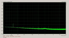
Here's what you can do with a bit of frequency tweaking.
You can get your units in a lot better.
-100dB - 0dBV FS
Attachments
The Twin T board keeps the notch of the first BEf between -30dB and -40dB depending on the frequency. Shibasoku is putting 5Vrmd into this filter. At that level -30dB is enough to raise the distortion of the buffer op amp at the output of the TT. So the distortion rises a bit at the peaks.
There may be some loss at the second harmonic with the BEF so perhaps that is compensation? (Seems like a long shot.)
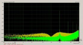
There was absolutely no shift in the harmonics when doing this adjustment.
The harmonic stay exactly the same. A test at various frequencies confirmed this.
No change.
Anyone have some spice models they care to share.
Currently I need an LME49990.
I'm sure there are other's I'll need as well.
Thanks,
Sync rename these. Take the .asc off.
Attachments
Last edited:
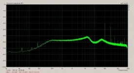
here is a test of the notch BEF filters. The probe i s on an output test point for the third BEF.
The total gain at this point is 26dB. 6dB at the input amplifier and 20 at the input to the second BEF. The test signal is 1kHz and the 725D has tuned to this frequency. The sampling is switched to Hold mode to prevent the notch frequency from changing.
A 10kHz signal is input and I added an attenuator at the Emu0204 input and normalized the 26dB gain to 0dBV FS. The signal is then tuned to 2kHz. As you can see the gain is 1.4dB @ 2kHz.
I've included the 10kHz as an overlay and displayed the 2kHz.
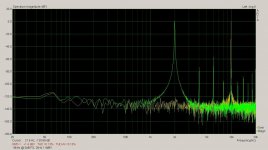
The second pic is the notch of the three BEF.
I don't see any issues at all. These filters are performing at spec with a darn good notch.
The error is all on the up side. The shoulder peaks at 2.7dB @ about 2.78 kHz, 1.5dB @ 3KHz, 0.8dB @ 4kHz and flattens out to 0dB from 5 kHz up.
The total gain at this point is 26dB. 6dB at the input amplifier and 20 at the input to the second BEF. The test signal is 1kHz and the 725D has tuned to this frequency. The sampling is switched to Hold mode to prevent the notch frequency from changing.
A 10kHz signal is input and I added an attenuator at the Emu0204 input and normalized the 26dB gain to 0dBV FS. The signal is then tuned to 2kHz. As you can see the gain is 1.4dB @ 2kHz.
I've included the 10kHz as an overlay and displayed the 2kHz.
The second pic is the notch of the three BEF.
I don't see any issues at all. These filters are performing at spec with a darn good notch.
The error is all on the up side. The shoulder peaks at 2.7dB @ about 2.78 kHz, 1.5dB @ 3KHz, 0.8dB @ 4kHz and flattens out to 0dB from 5 kHz up.
Attachments
I love windows 8.
I don't have permission to save the files.
When I figure out how to save it some time later
I'll have to figure out into which folders to place the
files. I found the location to place the .sub
into the .sub folder but no folder to place .asy period
Entering "add files to library" didnt find anything.
I''ll have to find some remedial users site to teach
me how to use windows now.
More and more I can no longer move files,
add or deletes files that I never had problems with.
Thank you Microsoft for making my life more difficult. : )
I love windows 8.
I don't have permission to save the files.
When I figure out how to save it some time later
I'll have to figure out into which folders to place the
files. I found the location to place the .sub
into the .sub folder but no folder to place .asy period
Entering "add files to library" didnt find anything.
I''ll have to find some remedial users site to teach
me how to use windows now.
More and more I can no longer move files,
add or deletes files that I never had problems with.
Thank you Microsoft for making my life more difficult. : )
The sub goes in the LT spice sub (sub circuit) folder in the lib folder.
The asy (assembly) goes in the LT spice sym (symbol) folder in the lib folder.
Last edited:
I love windows 8.
I don't have permission to save the files.
When I figure out how to save it some time later
I'll have to figure out into which folders to place the
files. I found the location to place the .sub
into the .sub folder but no folder to place .asy period
Entering "add files to library" didnt find anything.
I''ll have to find some remedial users site to teach
me how to use windows now.
More and more I can no longer move files,
add or deletes files that I never had problems with.
Thank you Microsoft for making my life more difficult. : )
Login as admin and check you permissions or check file permissions.
Win8 is extra secure by default. PITA.
David-
Excellent work. Its tedious but necessary. In the process could you confirm the meter readings? I think they were correct when I tested it but something was different from the 725 and I kept getting confused.
I traced the two trims for the cal check down. One for the dc offset on the TLO83 dual IC and the cal FS adjust. The meter was reading slightly high at FS so I trimmed it down to the 10 mark. The rest is a mastery without the manual and instructions. I don't want to mess with it much but does seem to calibrated.
Can you be more specific about check the meter readings?
What was weird about it?
Dick Moore found the scaling confusing when he was checking out the 725C before shipping it on to me.
Now I just have to figure out how I can do the marker test with what I have here.
I realized a method to get the marker signal into the 725D. If I use the two inputs of one of the balanced inputs, high and low. I can put the marker signal on the low side and the test signal on the high side of the XLR. Attenuate the the marker signal. Since the marker frequency is different the +/- diff won't cancel.
Last edited:
That was easy,
thanks David...
just a bit over two hours. : )
You'd think I was computer illiterate...
heck I used to go to the CP/M, Apple Core
and other user groups back in the day.
For you young'ens out there, CP/M was
what computers used as on operating
system before there was DOS.
thanks David...
just a bit over two hours. : )
You'd think I was computer illiterate...
heck I used to go to the CP/M, Apple Core
and other user groups back in the day.
For you young'ens out there, CP/M was
what computers used as on operating
system before there was DOS.
As I remember the 725C output was a little higher than my 725 on the same signal. Something I had to accommodate for when comparing. I'm using a FFT plug in in a Tek scope for most measurements with the stuff and the different levels did get me several times. Partly its the different ranging with the 725C having one lower step. I would use the display on the Boonton for the THD+N since its digital and gave me more flexibility in setting frequency range etc.
As I remember the 725C output was a little higher than my 725 on the same signal. Something I had to accommodate for when comparing. I'm using a FFT plug in in a Tek scope for most measurements with the stuff and the different levels did get me several times. Partly its the different ranging with the 725C having one lower step. I would use the display on the Boonton for the THD+N since its digital and gave me more flexibility in setting frequency range etc.
I think there is one or two bad relays in this 725D. Sometime it displays -120.9dBV and sometimes -117dBV for the same signal. if I switch inputs and back it drops down again.
Sometimes I have to turn the power off and on before the distortion drops. So there is some mechanical wear there.
I haven't noticed anything flaky about the meter. I'll put my 725C beside it tomorrow and compare the two. I'll take one more shot at getting the filter noise down. I have a replacement for that TLO74 used for the filters on this unit. The filter are switched with 74HC4051 analog multiplexer rather than relays as in the 725B/C.
Strangely some of the offset trims used on the TLO70 where tied to the wrong power rail for this IC. I had to rework some of the trim circuits for the op amps I put in. LT1468 uses PNP input transistors so trim is on negative rail. OPA134 is on the positive rail. The OPA134 loses PSRR when the offset trim is used so an RC filter has to be fit to the wiper pin to get the 60Hz down. Not so with the LT1468.
Last edited:
I too noticed relay contacts were sometimes not making good contact and gave varying readings..... it happens occasionally but not often enough for me to try find the offender.
Love that LT1468. A very versatile high perf opamp.
Leaving for Nepal and Thailand in a week.
THx-RNMarsh
Love that LT1468. A very versatile high perf opamp.
Leaving for Nepal and Thailand in a week.
THx-RNMarsh
Last edited:
There is a Shibasoku 725B up for sale on Ebay right now. Says from Japan
Shibasoku 725B Automatic Distortion Analyzer | eBay
Shibasoku 725B Automatic Distortion Analyzer | eBay
- Home
- Design & Build
- Equipment & Tools
- ShibaSoku Automatic Distortion Analyzer