That is with the back plate back on the boards.
How did you get your noise so low? That is looking good.
Okay pic coming up shortly.
Sync my oscillator is completely floating from ground. I spent a lot of time getting it to where it is. Unfortunately not all signal sources are this clean. Most of what you see on FFT as noise
is noise from differences between grounds of equipment connected to the analyzer and the analyzer ground. In practice it might not always be possible for the display to look this clean.
If I connect my scope ground to the analyzer the noise is injected. Even the ground difference between my analyzer and the ground and Richards 725D is enough to lose everything gained. The noise is back plus some. It is much improved to strap the input grounds of each analyzer together. A scope probe grounding between the two units is not good enough.
Here is the pic of the A3 board. I emailed you a larger
one if you need to zoom in on specific parts.
Hope this helps.

As to ideas for the 3H?
I'll cop out and ask if you checked the usual suspects.
Let me think about that while I try to swap boards
and see if the old McIntosh I'm working on is still working.
More stuff to do...while baby destroys the house.
Your A3 board doesn't have the factory mod of an additional capacitance neutralizer circuit.
Shibasoku added a piggyback op amp on top of U2 and a tiny 4mm x 4mm PCB with a trim cap on it beside U2. Other components point to point connected.
Unless Demian added this in?
I wonder where it is?
I went back and tried to find the piggy back opamp but I
didn't find it. Maybe it was a taller opamp. It looked like
one of the quad op amps was stacked upon another as its
pins were still full length, not sure what board it was on though.
can you sent a pic of the board and where it is affixed when
you get the chance.
Not too sure how to deal with ground issues.
How is it going? Did you review the well tempered clock
thread for getting the clock noise squared away?
Can we get a better clock? Or is the clock just
fine and its implementation can be improved.
Cheers,
Sync
I wonder where it is?
I went back and tried to find the piggy back opamp but I
didn't find it. Maybe it was a taller opamp. It looked like
one of the quad op amps was stacked upon another as its
pins were still full length, not sure what board it was on though.
can you sent a pic of the board and where it is affixed when
you get the chance.
Not too sure how to deal with ground issues.
How is it going? Did you review the well tempered clock
thread for getting the clock noise squared away?
Can we get a better clock? Or is the clock just
fine and its implementation can be improved.
Cheers,
Sync
Sync it's a low frequency clock 498Hz or so. The problem isn't with the clock just the fact that it is there and in the audio band. It's an integral part of the metering design. It's part of a different method of doing analog division rather using an analog multiplier ic. It actually does a better job of it. I have a paper some where on the method if your interested.
All that can be done and should be done is to try and isolate the clock. Finding the best ground path for return currents, shielding and possibly filtering the power rails to the clock.
Filtering power rails is not possible on the A6 board because there are relay drives on the board. The relay drivers require a fare amount of current. Filtering the rails would result in too much voltage drop across the R of an RC filter and then the relays won't activate.
One thing you can do is pull all the board and re-seat them repeating this a few times.This cleans the pins. Don't use contact cleaners in the Shibasoku. The contact cleaners spread
crap all over the place. Instruments are cleaned with isopropyl alcohol and Qtips in cal labs.
One thing you can do is pull all the board and re-seat them repeating this a few times.This cleans the pins. Don't use contact cleaners in the Shibasoku. The contact cleaners spread
crap all over the place. Instruments are cleaned with isopropyl alcohol and Qtips in cal labs.
Clock
I'd be interested in reading the article, when you find it.
Power Rails A6
Is it possible to filter after the relay drivers? or are they driving a
relay on another board?
Shielding
It is advisable to rewire some of the power supply wiring with
smaller shielded wire to help eliminate noise etc. I've got a
couple of reels of the silver mini coax cable. I think it is pretty
good stuff not sure how or where would be a good place.
Cleaning
Good info. I used Deoxit after I removed the battery board to removed the oxidation from it. Then I used various O-Hs to clean that off.
I've got three O-H grades, ethyl at 200 pure reagent grade, then
99.9999% iso, and a irradiated 70% iso with ultra pure H2O.
They are all very pure either laboratory grade or specialty grade stuff.
I've got the q-tips, the industrial wooden q tips, and two types
of wipes, Kim Wipe and poly type ELE wipes.
I lost the link to that site where you got those SOIC breakout boards.
When you get the chance can you post a link to that again. I think
it is up there in Canada too.
Cheers,
I see if I can find the paper on the analog multiplier/divider.
No on the rail filtering of the A6 board. It's not necessary if the ground is routed differently.
On the 725C I cut a trace on the A7 board and routed the ground to the power supply entry but the 725D is different.
No it's not necessary to rewire any of the power supply wiring. it wouldn't help. Shibasoku got it right.
I'll direct you to Chris Bridge (anatek) for why you shouldn't use anything but isopropyl alcohol on electronics electro mechanical parts and especially not on instruments. I have D5S but I rarely use it.
If you need to use something like that then the part needs to be replaced. Of course sometimes there is no replacement part. Isopropyl alcohol is far better at removing oxidation and doesn't leave anything behind. For cleaning flux off a PCB lacquer thinner is the absolute best.
The SOIC breakouts are available at OSH Park. Go to the user share area, Find the breakout you want and place an order for the PCBs. Far cheaper this way and the quality is as good or better.
Last edited:

Richard:
Those are impressive specs. So good they really need validation. Validation is quite difficult with the Shibasoku because you need to insert a harmonic at very close to the target frequency of a known level at a huge attenuation. When I first got the 725 I spent several days fussing at this because the numbers were so low I really didn't feel i could trust them.
What are you using as a source for these measurements?
Your A3 board doesn't have the factory mod of an additional capacitance neutralizer circuit.
Shibasoku added a piggyback op amp on top of U2 and a tiny 4mm x 4mm PCB with a trim cap on it beside U2. Other components point to point connected.
Unless Demian added this in?
I didn't add the piggyback mod. Given that its in the older units I think it was something of an oversight to have left it off. I was impressed that Shibasoku would do a mod like I would have.
I have noticed that the BEF filters are different in subtle ways on the different generation instruments and on the different stages. We should try to get the details in one place and see what changed and if its worth changing on other units.
We should also work out a proper alignment process for these. They would all benefit from a proper alignment at their vintages.
Just to drive everyone nuts there is an AM51 on eBay that is essentially a 725 + generator + IM test in one box. Shibasoku Audio Analyzer AM51A | eBay http://www.shibasoku.com/download/avc/am51c_e.pdf I cannot justify buying one at this price but it looks to be a really nice one stop solution.
Just to drive everyone nuts there is an AM51 on eBay that is essentially a 725 + generator + IM test in one box. Shibasoku Audio Analyzer AM51A | eBay http://www.shibasoku.com/download/avc/am51c_e.pdf I cannot justify buying one at this price but it looks to be a really nice one stop solution.
Yes but sold as non-working!
BTW your method of close spectra verification of harmonic levels is quite a good idea. On my project list is a very very low distortion oscillator and the issue was how to adjust it!
I didn't add the piggyback mod. Given that its in the older units I think it was something of an oversight to have left it off. I was impressed that Shibasoku would do a mod like I would have.
I have noticed that the BEF filters are different in subtle ways on the different generation instruments and on the different stages. We should try to get the details in one place and see what changed and if its worth changing on other units.
We should also work out a proper alignment process for these. They would all benefit from a proper alignment at their vintages.
Just to drive everyone nuts there is an AM51 on eBay that is essentially a 725 + generator + IM test in one box. Shibasoku Audio Analyzer AM51A | eBay http://www.shibasoku.com/download/avc/am51c_e.pdf I cannot justify buying one at this price but it looks to be a really nice one stop solution.
I still have Richard analyzer here. I can set up such a test just need a good stage to do an injection. I have the 339 oscillator and an HP 652A. The distortion of the second test oscillator really doesn't matter for this verification. Victor had pretty good set up for doing this test on his oscillator but I can't find the schematic for it.
I can inject before the the first gain stage on the Twin T board. There is a test point that will work as a summing point into the +10 gain stage. Just need a set up.
Any suggestions?
The part that drove me nuts- first it has to be essentially locked and then hum and grounding. . . I used the Boonton since it works as a crystal locked synthesizer and is extremely stable for the harmonic. It also has a good attenuator. I coupled that to an external 100 dB attenuator (getting to 110 or 120 dB with accuracy is very difficult). The attenuator used a short piece of wire as the shunt and I tweaked it with a micro-ohmmeter. Stray capacitance can seriously alter he HF response so construction needs to be very carefully done. I now know why RF attenuators are so expensive and why -90 dB ones don't exist.
After David tuned the BEF's, the THD+N is -127dBV.
WoW!
THx-RNMarsh
WoW!
THx-RNMarsh
David has reduced the noise and distortion significantly for me to get these new specs from my 725D:
-140dBV THD
-121dBV THD+N
Here is data at monitor port; FS @ 0dBV = -110dBV FS
View attachment 493231
THx-RNMarsh
After David tuned the BEF's, the THD+N is -127dBV.
WoW!
THx-RNMarsh
Not really. It was a miscalculation.
Actually that's pretty suspicious. The BEF's have like a 1% bandwidth so unless the fundamental was way high reducing it should not make a big difference.
What was it before and after the tuning? Relative to the overall noise floor in 30 KHz band a 6 dB reduction is like halving the input noise from 5 nV to 2.5 nV, which is not going to happen easily.
As soon as I can clear some space I'll explore tweaking the BEF's.
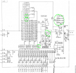
Attached is a typical BEF for Shibasoku. The green circles are the trims. The trimmer resistors have a significant impact on the gain (from playing with the sim) so you need a process to get them right. Also attached is the sim I built of the BEF.
What was it before and after the tuning? Relative to the overall noise floor in 30 KHz band a 6 dB reduction is like halving the input noise from 5 nV to 2.5 nV, which is not going to happen easily.
As soon as I can clear some space I'll explore tweaking the BEF's.
Attached is a typical BEF for Shibasoku. The green circles are the trims. The trimmer resistors have a significant impact on the gain (from playing with the sim) so you need a process to get them right. Also attached is the sim I built of the BEF.
Attachments
Actually that's pretty suspicious. The BEF's have like a 1% bandwidth so unless the fundamental was way high reducing it should not make a big difference.
What was it before and after the tuning? Relative to the overall noise floor in 30 KHz band a 6 dB reduction is like halving the input noise from 5 nV to 2.5 nV, which is not going to happen easily.
As soon as I can clear some space I'll explore tweaking the BEF's.
Attached is a typical BEF for Shibasoku. The green circles are the trims. The trimmer resistors have a significant impact on the gain (from playing with the sim) so you need a process to get them right. Also attached is the sim I built of the BEF.
The first BEF on the 725D is a Twin T. The second and third are Bridged T. So the 725D is a bit different. I'm not tuning the resistor trims just the frequency centers which were out a bit causing the notch depth to be a bit high in some ranges. The resistor trims will change the envelope and bandwidth of the filters so best to leave them alone. that's why you see a gain change. Since they all work together it would be a bitch to get them back in.
And that with the instructions. I'll still check on the tuning on mine at some point. There is one trim for the 1K to 10K range and two for the 10K to 100K in that filter.Since they all work together it would be a bitch to get them back in.
- Home
- Design & Build
- Equipment & Tools
- ShibaSoku Automatic Distortion Analyzer