Re: output impedance question
Hey.
If you go back to beginning of this SEWA thread (maybe first or second page)
The Output Impedance was discussed in several posts.
And they got to some figure.
It might also have been in OTA-thread.
If you can not find those posts, Mad_K will tell you the output impedance.
Tyimo said:Hi Mads!
Could you tell me what is the correct output impedance of the SEWA and the OTA amps??
Greets: Tyimo
Hey.
If you go back to beginning of this SEWA thread (maybe first or second page)
The Output Impedance was discussed in several posts.
And they got to some figure.
It might also have been in OTA-thread.
If you can not find those posts, Mad_K will tell you the output impedance.
Hi Lineup!
Sorry, but there is only about input imp of SEWA and output imp of the preamps..... if I looked well.
My question is: what is the output imp of the SEWA power amp.")
I know I should measure it, but it would be very uncomfortable for me. (Signal generator is far from the amp.....) May be your simulator program could tell us?
Greets:
Tyimo
If you go back to beginning of this SEWA thread (maybe first or second page)
The Output Impedance was discussed in several posts.
Sorry, but there is only about input imp of SEWA and output imp of the preamps..... if I looked well.
My question is: what is the output imp of the SEWA power amp.
I know I should measure it, but it would be very uncomfortable for me. (Signal generator is far from the amp.....) May be your simulator program could tell us?
Greets:
Tyimo
Re: output impedance question SEWA OTA
I might have an old brain.
But there is Not often anything wrong with Lineup Remembering
... in 20 years from now, when I am 75 years old, we will see.
... but now, no big problems - Lineup Memory better than many young
OTA - One Transistor Amplifier
See Posts #56 - 88.
They tell How to calculate approximate Output Impedance of OTA.
Now, you know that OTA and SEWA are brothers.
They are same circuit!
Which means ................ what ...... ?
Regards
lineup
lineup said:
Hey.
If you go back to beginning of this SEWA thread (maybe first or second page)
-----------------
It might also have been in OTA-thread.
I might have an old brain.
But there is Not often anything wrong with Lineup Remembering
... in 20 years from now, when I am 75 years old, we will see.
... but now, no big problems - Lineup Memory better than many young
OTA - One Transistor Amplifier
See Posts #56 - 88.
They tell How to calculate approximate Output Impedance of OTA.
Now, you know that OTA and SEWA are brothers.
They are same circuit!
Which means ................ what ...... ?
Regards
lineup
Tyimo said:My question is: what is the output imp of the SEWA power amp.
Believe or not
Output impedance (without the speaker load) is the paralleled
resistance between 1/gm(transconductance of the fet) and the total resistance below the source.
Thanks Lineup!!!
I found it! You have realy good memory.
Thanks for Babowana too!
So, am I right: OTA output imp will be with 10R source load and IRFP150 Gfs14 ca. 70milliohm??
How can I calculate with common source amps?
Greets:
Tyimo
I found it! You have realy good memory.
Thanks for Babowana too!
Output impedance (without the speaker load) is the paralleled
resistance between 1/gm(transconductance of the fet) and the total resistance below the source.
So, am I right: OTA output imp will be with 10R source load and IRFP150 Gfs14 ca. 70milliohm??
How can I calculate with common source amps?
Greets:
Tyimo
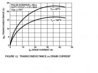
I can see no value
in the datasheet, called 1/gm
and no curve using this term, either
'Forward transconductance' of IRFP150N is 14 S ( 13 S for IRFP150 ) at 25V 22 Ampere
Datasheets dirctly from International Rectifier:
IRFP150 or IRFP150N ... take your pick!
http://www.irf.com/product-info/datasheets/data/irfp150.pdf
http://www.irf.com/product-info/datasheets/data/irfp150n.pdf
As for output impedance of OTA, Mad_K guess was 0.25 Ohm
and should be lower for Seven Watt SEWA
lineup
Thanks Mads and Lineup!
I havn't got any educated guess......
If I would measure it should I like this:
Output impedance=(Load resistance*(Vunloaded minus Vloaded))/Vloaded
Tyimo
you'll have to make some educated guess or measure it for these low currents
I havn't got any educated guess......
If I would measure it should I like this:
Output impedance=(Load resistance*(Vunloaded minus Vloaded))/Vloaded
Tyimo
Tyimo said:Thanks Mads and Lineup!
If I would measure it should I like this:
Output impedance=(Load resistance*(Vunloaded minus Vloaded))/Vloaded
Tyimo
That is the best way, practical measuring, two times, with different loads. The output voltage will sink with a value that is proportional to the loading.
Maybe theoretical calculations can come close to same value.
But we also know that no 2 devices are alike.
Which also means,
that no 2 amplifiers even from same schematic are the precisely the same.
Even 1 % resistors can be +/-1% different ( 2% span ).
And are many resistors in an amplifier.
lineup
I meant guess or measure the transconductance Gfs (gm) IRFP250N has 17S @50V/18A. Let's guess it has 3S at 15V/3A. Output Z would be 1/3S // CCS (very large number) // 1K (bleeder) // 8ohm (load) = somewhere around 0,3ohm.
To measure the output impedance:
Apply a 1KHz sinus for 10V output into your scope. Attach a load (10R for example). If you are measuring 9,5V across the load, your output impedance is what makes this voltage drop
Edit: your formula is correct Tyimo
To measure the output impedance:
Apply a 1KHz sinus for 10V output into your scope. Attach a load (10R for example). If you are measuring 9,5V across the load, your output impedance is what makes this voltage drop
Edit: your formula is correct Tyimo
Re: output impedance question
Tyimo
one thing I have wondered is
Why do you want to know output impedance of your SEWA?
Like Nelson Pass, sometimes 'The One and Low DampingFactor Man',
I don't worry about output impedance,
as long as my amplifier will have a good performance - at work
We have discussed damping factor in a long topic some years ago.
My opinion told in beginning of thread,
was later in thread backed up
by Nelson Pass telling his experiences on damping factors, in his amps.
Regards, lineup
Tyimo said:Hi Mads!
Could you tell me what is the correct output impedance of the SEWA and the OTA amps??
Greets: Tyimo
Babowana said:
Output impedance (without the speaker load) is the paralleled
resistance
between 1/gm(transconductance of the fet) and the total resistance below the source.
Tyimo
one thing I have wondered is
Why do you want to know output impedance of your SEWA?
Like Nelson Pass, sometimes 'The One and Low DampingFactor Man',
I don't worry about output impedance,
as long as my amplifier will have a good performance - at work
We have discussed damping factor in a long topic some years ago.
My opinion told in beginning of thread,
was later in thread backed up
by Nelson Pass telling his experiences on damping factors, in his amps.
Originally posted
by lineup
11th July 2002 11:58
nothing to pay any greater notice
Damping factor is something I never
understood either.
A welldesigned amplifier doesn't have to worry
about damp factor.
Regards, lineup
- Status
- This old topic is closed. If you want to reopen this topic, contact a moderator using the "Report Post" button.
- Home
- Amplifiers
- Pass Labs
- SEWA - Seven Watt Amplifier