Tyimo said:O.K.! Thanks!")
But where and how to put the trimmer?
Parallel with the source?
Tyimo
hmmm - i have no idea
... maybe i should know this ...
DC offset adjust
Hi Lineup!
O.K. I open my question :
If I would use paralelled, non matched pair of MosFets in the SEWA (or it's balanced version) where to put a trimmer to adjust the correct DCoffset voltage???? I know in the SOZ we could use a ca. 100R resistor paralell with R5-R6 on the Source. But the SEWA is quiet different amp.....
Tyimo
Hi Lineup!
hmmm - i have no idea ... maybe i should know this ...
O.K. I open my question
:If I would use paralelled, non matched pair of MosFets in the SEWA (or it's balanced version) where to put a trimmer to adjust the correct DCoffset voltage???? I know in the SOZ we could use a ca. 100R resistor paralell with R5-R6 on the Source. But the SEWA is quiet different amp.....
Tyimo
Balanced SEWA's trimmerpot
Hey Mads and Lineup!
Nothing news for my Balanced SEWA with unmatched pair of Mosfets trimer question??
I know this method:
If you are unable to find input devices matched to within 30mV, you must insert resistance in the source to make up the difference. The resistance is calculated by the difference of the two values of VGS divided by 5mA. For example, if the difference in VP1GS is 100mV, then 0.1/0.005 = 20Ù. You would then place 20Ù in series with the MOSFET source having the lower VGS.
But, what do you think about this idea:
I could put a trimmerpot in series with R10 (refering to the original SEWA V1 schematic) for setting the Drains voltage and so the Source voltage too and also for precise setting the the offset voltage on the output of the amp. This way I built my 20W Balanced Zenamp and it works wery well.
What is your oppinions? Would it be good?
What would be the best value of the trimmer? 5K?
Tyimo
I know
many use trimmer to balance JFET input pairs.
you can see this in absolute top class audio amplifiers, too.
At least when talking BJT, bipolar like BC550C etc,
I know that it is important to share current EXACTLY 50%-50%
from the tail, from the current source.
( see Douglas Self investigations and papers )
I see many other say the same thing - make sure have same current in both input transistors.
I cant see no reason, why is different when using JFET.
I also see that those into high quality JFET input amplifiers
alway use a close matched pair.
And most usually they do this the easy way
- but to a little bit of extra cost:
Buy some 2SK389 = Two close Matched JFET in same package!
If you compare the cost when buying 10 pcs K389 (will give you 10 very good amplifiers!)
with the cost of Chassis, Transformer, Power Supply electrolyts and Heatsink
..... it is really nothing
... semiconductors are always the low cost
in an amplifier .... if you count for a complete amp.
Quote from another forum:
2SK389 will be obsolete in near future,
so it is worth to have spare parts
SK389 is most common such matched JFET pair,
but there are others too - among these some good Small ones (SO8).
Sure is there will be coming even better replacements for 2SK389!
If not already made ...
Extremely good JFETs:
http://www.calogic.net/html/jfetdual.html
This one has got some MOSFETs dual - but not JFET, I think
http://www.centralsemi.com/index.aspx
=============================================
We are in Nelson Pass forum.
Hear the words from the master
Lowering the Noise
Part of having low noise is either having high power supply rejection
(PSRR) or a quiet power supply. It is not difficult to use quiet current
sources or a quiet power supply or both.
After that, the noise will depend heavily
on the quality of the input transistors.
For even lower noise, it is possible to use low noise JFets as the
differential pair, giving random input noise on the order of .4 microVolts.
Fig. 16 shows the circuit of Fig. 8 but with 2SK389 dual low noise JFets
dropped in. The distortion and noise at low levels drops by an order of
magnitude, but the performance at higher levels is nearly identical, as
seen in Fig. 17.
http://www.passdiy.com/pdf/diyopamp.pdf
===============================================
Here is another specialist in JFET PreAmplifiers
http://www.forsselltech.com/schematics.htm
===============================================
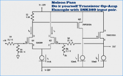
I attach Nelson Pass figure, showing a typical input differetial
for making your own discrete JFET Op-Amp.
lineup
many use trimmer to balance JFET input pairs.
you can see this in absolute top class audio amplifiers, too.
At least when talking BJT, bipolar like BC550C etc,
I know that it is important to share current EXACTLY 50%-50%
from the tail, from the current source.
( see Douglas Self investigations and papers )
I see many other say the same thing - make sure have same current in both input transistors.
I cant see no reason, why is different when using JFET.
I also see that those into high quality JFET input amplifiers
alway use a close matched pair.
And most usually they do this the easy way
- but to a little bit of extra cost:
Buy some 2SK389 = Two close Matched JFET in same package!
If you compare the cost when buying 10 pcs K389 (will give you 10 very good amplifiers!)
with the cost of Chassis, Transformer, Power Supply electrolyts and Heatsink
..... it is really nothing
... semiconductors are always the low cost
in an amplifier .... if you count for a complete amp.
from LSK389 datasheet:
http://www.linearsystems.com/datasheets/LSK389.pdf
Matching. VGS-VGS2 Differential Gate to Source Cutoff Voltage:
Max 20 mV ( 0.020V at 1mA current in each JFETs )
.
Quote from another forum:
2SK389 will be obsolete in near future,
so it is worth to have spare parts
SK389 is most common such matched JFET pair,
but there are others too - among these some good Small ones (SO8).
Sure is there will be coming even better replacements for 2SK389!
If not already made ...
Extremely good JFETs:
http://www.calogic.net/html/jfetdual.html
This one has got some MOSFETs dual - but not JFET, I think
http://www.centralsemi.com/index.aspx
=============================================
We are in Nelson Pass forum.
Hear the words from the master
Lowering the Noise
Part of having low noise is either having high power supply rejection
(PSRR) or a quiet power supply. It is not difficult to use quiet current
sources or a quiet power supply or both.
After that, the noise will depend heavily
on the quality of the input transistors.
For even lower noise, it is possible to use low noise JFets as the
differential pair, giving random input noise on the order of .4 microVolts.
Fig. 16 shows the circuit of Fig. 8 but with 2SK389 dual low noise JFets
dropped in. The distortion and noise at low levels drops by an order of
magnitude, but the performance at higher levels is nearly identical, as
seen in Fig. 17.
http://www.passdiy.com/pdf/diyopamp.pdf
===============================================
Here is another specialist in JFET PreAmplifiers
http://www.forsselltech.com/schematics.htm
===============================================
I attach Nelson Pass figure, showing a typical input differetial
for making your own discrete JFET Op-Amp.
lineup
Attachments
You can not adjust unmatched paralelled mosfets with a pot. You should match paralelled devices. In a pinch one could put resistors in paralell with the source resistors, but I wouldn't design for it.
When designing a balanced version I would use a pot instead of the lower resistor in the bias setting divider to get correct dc offset. This way you can get rid of the output coupling caps.
When designing a balanced version I would use a pot instead of the lower resistor in the bias setting divider to get correct dc offset. This way you can get rid of the output coupling caps.
When designing a balanced version I would use a pot instead of the lower resistor in the bias setting divider to get correct dc offset.
Yeeesss! This is what am I saying!
A trimmer in series or instead of R10 (10K). Whatn would be the best adjustable value of the trimmer? 20K?
Thanks Mads!
Greets:
Tyimo
Tyimo,
Are you going to use a BOSOZ as a preamp to drive your balanced Sewa?
I was thinking about a balanced sewa as well, but I'll wait for you to build one and report about the sonic impressions
Go ahead, it should make for a potentialy very good sounding amp!
Regards,
Vix
Are you going to use a BOSOZ as a preamp to drive your balanced Sewa?
I was thinking about a balanced sewa as well, but I'll wait for you to build one and report about the sonic impressions
Go ahead, it should make for a potentialy very good sounding amp!
Regards,
Vix
Hi Mads!
Thanks.
Vix!
Yes, but first I have to modificate the BOSOZ for 2SK216.
O.K. just give me a couple of weeks or months......
Greets:
Tyimo
Thanks.
Vix!
Are you going to use a BOSOZ as a preamp to drive your balanced Sewa?
Yes, but first I have to modificate the BOSOZ for 2SK216.
I was thinking about a balanced sewa as well, but I'll wait for you to build one and report about the sonic impressions
O.K. just give me a couple of weeks or months......
Greets:
Tyimo
Tyimo said:O.K. It is nice what you wrote, but Who spoke about input differencial Jfets?!
I was asking about the trimmer idea to use in a balanced SEWA configuration.....
And yes, I will by some 2SK389.....
Tyimo
sorry Tyimo
i didn't know what i was talking about
well,
my post wasnt wasted ... some use for it ... for someone, I hope
 lineup
What mod is that?Shift 2 legs?Yes, but first I have to modificate the BOSOZ for 2SK216.
sorry Tyimo
No problem Lineup!
The problem already solved.What mod is that?Shift 2 legs?
Not only....
The 2SK216 has different Vgs (1.5V!)Tyimo

A question a bout double j-fets..
Are 2SK389 or some of this http://www.calogic.net/html/jfetdual.html
Useful as a diff input stage in for example a Mini-Aleph?
Are 2SK389 or some of this http://www.calogic.net/html/jfetdual.html
Useful as a diff input stage in for example a Mini-Aleph?
SEWA PCB's
Are there any SEWA pcb's available ?? I am unable to email due to moderation policies. Apparently I need more posts!! I have built the ZV4 and am amazed at the musicality. Need a second amp for bi-amp setup and sewa looks like the guy. Can do it P2P but the board of course simplifies things.
Thanks for any info.
- Status
- This old topic is closed. If you want to reopen this topic, contact a moderator using the "Report Post" button.
- Home
- Amplifiers
- Pass Labs
- SEWA - Seven Watt Amplifier