Hi,Hi,
Yes, can replace with LM311 (this is only faster).
Cut-Off is Independent from Vcc.
function is immediately disable SD.
my help is difficult without your schematic.
If you put on this thread, I can control everything.
I have correctly understood that at deenergizing of the amplifier this scheme creates SD a signal for closing of the driver and prevention of an impulse of deenergizing, +V is connected to a conductor of a +Vcc(12V) of the driver and logic? You tried this scheme in practice what results were? While there is no time to draw the scheme with corrections, I can later.
I know that R13 not gate the resistorR13 is NOT a gate resistorGate resistors in your schematic are R15 and R16. But I would not change them...
Yes
, but AP2 wrote that it influences on DT, therefore I have assumed that it is possible to improve parametres of the amplifier having reduced this resistor a little.Now I conduct tests and I enjoy a soundhello vogor,
To what extent is the amp?
After you've made circuit with LM?
I will try schemes of smooth deenergizing later.ok,this LM-circuit disable SD fast (when switch-Off psu).
also You can adj R17(47K on LM-Circuit) to regulate time-Cutoff.
(yes ,connect to vc-driver).
For You R13...I not see...
you referring to the speech before? (PWM-sides adj).
if this, you can see that the variation of the THD even at high frequencies (Audio).
You have instruments?
also You can adj R17(47K on LM-Circuit) to regulate time-Cutoff.
(yes ,connect to vc-driver).
For You R13...I not see...
you referring to the speech before? (PWM-sides adj).
if this, you can see that the variation of the THD even at high frequencies (Audio).
You have instruments?
ok,this LM-circuit disable SD fast (when switch-Off psu).
also You can adj R17(47K on LM-Circuit) to regulate time-Cutoff.
(yes ,connect to vc-driver).
For You R13...I not see...
you referring to the speech before? (PWM-sides adj).
if this, you can see that the variation of the THD even at high frequencies (Audio).
You have instruments?
AP2, schematics is on the first page of this topic. There was changed almost nothing. Only removed T2 and inserted 200K resistor between +65V and Vb pin of driver, so you can refer to it...
Last edited:
Now I conduct tests and I enjoy a sound
Do not forget to post the photos of your amp and PCB for us please!!!
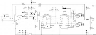


To what level limit an entrance signal two diodes on an input? There is an assumption that they will not allow to receive a total power and too early begin restriction. I am going to connect the lamp preliminary cascade but it is not assured of value of sensitivity of the amplifier, a signal I take from an analogue exit of a sound card of the computer.
To what level limit an entrance signal two diodes on an input? There is an assumption that they will not allow to receive a total power and too early begin restriction. I am going to connect the lamp preliminary cascade but it is not assured of value of sensitivity of the amplifier, a signal I take from an analogue exit of a sound card of the computer.
They do limit differential voltage between + and - inputs of opamp to about +/-0.7 Volts. But under normal operation these diodes do not limit signal at all, because the input signal will be always compensated to near zero by negative feedback at opamp inputs.
These diodes would limit the input music signal if they would be placed before R2. But they are placed after R2 so they are used only to protect opamp inputs at amp startup and shutdown, when there is nothing connected to the amp input...
With 48K NFB resistor (R3+R18) and with 2.2K input resitor the amp amplifies signal about 20 times. With 1V input signal you will get about 20V output signal. So to get the full output power with +/-65V rails you need about 2Vrms input signal.
Last edited:
I thank for an explanation, but it is possible more in detail why they will not limit an entrance signal above 0,7V if they stand after resistor R2, in what a difference?They do limit differential voltage between + and - inputs of opamp to about +/-0.7 Volts. But under normal operation these diodes do not limit signal at all, because the input signal will be always compensated to near zero by negative feedback at opamp inputs.
These diodes would limit the input music signal if they would be placed before R2. But they are placed after R2 so they are used only to protect opamp inputs at amp startup and shutdown, when there is nothing connected to the amp input...
With 48K NFB resistor (R3+R18) and with 2.2K input resitor the amp amplifies signal about 20 times. With 1V input signal you will get about 20V output signal. So to get the full output power with +/-65V rails you need about 2Vrms input signal.
I thank for an explanation, but it is possible more in detail why they will not limit an entrance signal above 0,7V if they stand after resistor R2, in what a difference?
I have written it already: because the input signal will be always compensated to near zero by negative feedback at opamp inputs.
If in some moment at the input of amp (before R2) there will be +1V, then at amp output (after L1) there will be about -10V. And using the Ohms Law it is possible to calculate, that between R2 and R3 there will be near zero voltage at opamp inputs...
Precisely to say, the input signal will be mainly compensated via NFB, and the ripple current will be compensated via C2 and C3, but it is simplier to understand it, assuming that input signal will be compensated alone via global NFB
Last edited:
Somehow strange it turns outI have written it already: because the input signal will be always compensated to near zero by negative feedback at opamp inputs.
If in some moment at the input of amp (before R2) there will be +1V, then at amp output (after L1) there will be about -10V. And using the Ohms Law it is possible to calculate, that between R2 and R3 there will be near zero voltage at opamp inputs...
Precisely to say, the input signal will be mainly compensated via NFB, and the ripple current will be compensated via C2 and C3, but it is simplier to understand it, assuming that input signal will be compensated alone via global NFB
, if on an amplifier input will be 2V that at factor of strengthening K=20 - on an exit should be 40V but how it is possible if these limiting diodes do not allow be formed potential differences between inputs opamp more than 0,7V I can not to understand why they will not limit a signal.- Status
- This old topic is closed. If you want to reopen this topic, contact a moderator using the "Report Post" button.
- Home
- Amplifiers
- Class D
- Self-oscillating class D amplifier