Thanks! I am very gladCongratulations! well done!
I do not understand, why there can appear 3V at amp output appear, but it makes no sense anymore, since you solved the problems with POP and startup
Probably problem of deenergizing arises because of different speed of recession of feeding pressure for the amplifier and the separate stabilizer on 12V for the driver and logic, it would be interesting to see your variant of the scheme of deenergizing of the driver, it is possible on contact@svpremvs.ccI think it is needed to generate the shutdown signal for IR2110 driver. For example, if the -V source is less than 15-20 Volts, then generate shutdown. If you need an example circuit for it, I try to paint
Experiments only have begunWell, if you want to experiment with it, just do it!Theoretically it will work, but practically there are usually a lot of issues...


The scheme for a unipolar PSU I will draw a bit later, I can send to you on usual email.I suggest, that you try to paint the schematic for unipolar amp yourself first, and I will try to find errors then
Last edited:
it would be interesting to see your variant of the scheme of deenergizing of the driver
It is not needed to deenergize the driver, it is needed to shutdown it, using SD pin of IR2110.
Experiments only have begun
Do not broke too much of mosfets, otherwise experiments will be too expensive
The scheme for a unipolar food I will draw a bit later, I can send to you on usual email.
post it simply here, maybe other peoples will help you too then
Hi AP2, The scheme will be a bit later if I have cleaned short that T2, the making impulse of start and has connected Vb the driver to +Vc through the resistor 200K.Hi Vogor,
is possible see last revision of you schematics?( for this problem and for redesign new ritch FB. (for unipolar supply))
regards
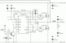
In your scheme signals on Hin and Lin the driver go on another (on the contrary) and there are resistors 220R how it works? You had problems with start/deenergizing in this scheme (impulses on an exit did not appear)? For what FB-2? What principle of work "Potenz/startup Delay", mosfet's gate should incorporate with-Vc through a time interval for driver start? If to increase the resistor 1,5K that will occur with DT will grow or will go down?This is the output stage of my old project (2003).
component values are adjusted to obtain a good reproduction even at low audio frequency (40Hz) at power, and less noise as possible.
also the resolution at high frequencies sound is excellent.
nothing special, with this driver (IR2110 I used). I think they are all similar. Regards
Last edited:
I did not understand anything.
modify for bridge amp single supply is used to "Vogor" or "81bas"?
Vogor want to have a unipolar bridged class D amp
For "smooth" deenergizing of the amplifier it is strong necessary to switch off at first the driver and then other power supply, it is possible to see an example of simple realisation of the given decision?It is not needed to deenergize the driver, it is needed to shutdown it, using SD pin of IR2110.
Do not broke too much of mosfets, otherwise experiments will be too expensive
post it simply here, maybe other peoples will help you too then
Yes, and with a power supply - straightened voltage of a network (AC220V).Vogor want to have a unipolar bridged class D amp
For "smooth" deenergizing of the amplifier it is strong necessary to switch off at first the driver and then other power supply, it is possible to see an example of simple realisation of the given decision?
It is here
Attachments
Thanks for a good and simple example, I will try. But it would be desirable to understand all the same because of what there is an impulse, after all a driver PSU falls down almost as smoothly as well as the main voltage?It is hereAfter switching the amp ON, two resistors (100K and 4.7K) will produce about 0.8V at T3 base. T3 will open and remove the SD signal from driver. Amp will start. When switching the amp OFF, the -V voltage will slowly fall down, and at about 15-20V transistor T3 will close again and produce the SD signal. So the driver will be disabled, when the power supply will be 'deenergized' to about 15-20V... Maybe it will be needed to vary the 100K resistor between 150-200K to get the desired effect

ok, ... old schematic has a modulator (not self Oscillator)
have out relay. Delay is a quick startup time for balanced modulator, after this, enable drive MOSFET.(at switch-off,use this for off driver)
220R attenuated glish (not influence the wave becouse input-2110 is high impedance).(this res is in relation with pcb, gndPlane etc..)
1.5 K and BJT is critical stage (many do not know) this is liable (if the previous stage is very good, fast rise-fail time) of good sound reproduction at high frequencies (usually many class D seems to mp3).
this resistors can adjust the sides of the PWM.
it is clear that if you put on a 10K open-collector at 300kHz rise-time it will be very slow.
with 100R is very fast (but power dissipation increments) this is normal.
1.5 K with bcx53 I got very good resolution on sound.
Obviously, the modulator is very good.
have out relay. Delay is a quick startup time for balanced modulator, after this, enable drive MOSFET.(at switch-off,use this for off driver)
220R attenuated glish (not influence the wave becouse input-2110 is high impedance).(this res is in relation with pcb, gndPlane etc..)
1.5 K and BJT
this resistors can adjust the sides of the PWM.
it is clear that if you put on a 10K open-collector at 300kHz rise-time it will be very slow.
with 100R is very fast (but power dissipation increments) this is normal.
1.5 K with bcx53 I got very good resolution on sound.
Obviously, the modulator is very good.
Thanks for a good and simple example, I will try. But it would be desirable to understand all the same because of what there is an impulse, after all a driver PSU falls down almost as smoothly as well as the main voltage?
The impulse is generated, because opamp is switched off before driver and mosfets are 'deenergized'... for example at +/-10 volts the opamp wil get too low voltage through 1.8K resistors and will not work anymore, although there is still a lot of energy at output mosfets. Oscillation stops and since the output can be only in two states (-V or +V), the strong impulse is generated.
It all means that with increase in this resistor increases DT?ok, ... old schematic has a modulator (not self Oscillator)
have out relay. Delay is a quick startup time for balanced modulator, after this, enable drive MOSFET.(at switch-off,use this for off driver)
220R attenuated glish (not influence the wave becouse input-2110 is high impedance).(this res is in relation with pcb, gndPlane etc..)
1.5 K and BJTis critical stage (many do not know) this is liable (if the previous stage is very good, fast rise-fail time) of good sound reproduction at high frequencies (usually many class D seems to mp3).
this resistors can adjust the sides of the PWM.
it is clear that if you put on a 10K open-collector at 300kHz rise-time it will be very slow.
with 100R is very fast (but power dissipation increments) this is normal.
1.5 K with bcx53 I got very good resolution on sound.
Obviously, the modulator is very good.
It all means that with increase in this resistor increases DT?
NO, this will only increase delay in PWM signal...
DT (dead time) can be only slightly corrected by gate resistors...
Ok, I in an amplifier PSU have two "banks" - 47000mFx80V, ballast resistors now for opamp - 2x2,7K/2W and for a PSU of the driver and logic the separate stabilizer 7812+200mFx16V, will try reduce condenser capacity (200mF) can driver will be closed faster and will not be output impuls.The impulse is generated, because opamp is switched off before driver and mosfets are 'deenergized'... for example at +/-10 volts the opamp wil get too low voltage through 1.8K resistors and will not work anymore, although there is still a lot of energy at output mosfets. Oscillation stops and since the output can be only in two states (-V or +V), the strong impulse is generated.
What mean is "internal UVLO" and "good circuit es. lm393 used at Window comparator"Big.."bumb" at switch-off is internal UVLO on IR2110.
one good circuit es. lm393 used at "Window comparator" can disable immediatelly
SD-driver.
Ok, I in an amplifier PSU have two "banks" - 47000mFx80V, ballast resistors now for opamp - 2x2,7K/2W and for a PSU of the driver and logic the separate stabilizer 7812+200mFx16V, will try reduce condenser capacity (200mF) can driver will be closed faster and will not be output impuls.
You can try it, but I think this will not help, because the driver will stop work LATER than opamp anyway.
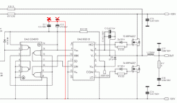
Also, do not forget about the error with caps (see my previous post).
- Status
- This old topic is closed. If you want to reopen this topic, contact a moderator using the "Report Post" button.
- Home
- Amplifiers
- Class D
- Self-oscillating class D amplifier

