Have you applied wood sealer before stain?
No. Yet another lesson learned the hard way. I didn't use stain per se, but I guess the dyed lacquer would have benefited from sealer as well. The finish isn't that bad though, I'm not unhappy with it. It's just that I know I could have done a lot better.
In any case, at this time I won't be redoing the finish. If I'd do that, I would most definitively fix the filleting and some other details in the woodwork before refinishing. Right now I just enjoy listening to the speaker I've assembled and in a couple of days the second one as well, too much so to force myself to disassemble and start doing the cabinets all over again.
")
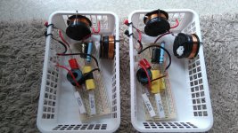
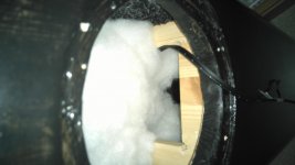
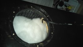
The both speakers are assembled now, drivers connected with abikos so I can adjust the amount of filling, length of ports etc. The cabinets are about half filled with polyester wadding, 500 g each approx 40 liter cabinet, so the filling as in the original Idunn. There's clearance from woofers to reflex ports, no filling between them.
I noticed that the thin connector wires in the XO breadboard assembly were adding too much resistance: the lowest impedance dip was at about 6 ohms instead of the 4 ohms it should be. I reassembled the breadboard XOs with thicker wires.
First impressions, speakers about 180 cm apart, toed in, listening distance about 200 cm from each speaker, giving an angle between the speakers of about 53°. Speakers about 50 cm apart from the back wall, the right one near side wall, the left one 200 cm apart from another side wall (dictated by our living room furnishing):
Crazy good imaging, something totally else than my previous diy speakers. Wide soundstage, beyond speaker width. Very immersive! Overall good balance. There's some minor harshness, I'd guess at around 4 kHz. There's also some minor muddiness of bass. A very good starting point to work with XOs and possibly some cabinet tuning details. The speakers are already at this point generally very pleasant to listen.
The newest U18RNX/P, straight from Seas factory, measured at clearly lower Fs than the other woofers, 47.9 Hz @ 1.6 Vrms, compared to the 51-52 Hz of the others at same voltage. I sent today an inquiry of the Fs discrepancies to Hifitalo and they forwarded it to Seas.
Attachments
I got a reply from Seas:
"The resonance frequency is accepted within ±10% from the golden reference. The resonance of the golden unit is 49Hz when measured cold. This driver has never been run hot, so that it stays with the same parameters as the drivers that come from the production line. All of these drivers are well within spec. "
Attached: my measurements of the driver impedances.
Attachments
Last edited:
The speakers sound better now, the muddiness is gone. I haven't remeasured the woofers yet for I don't want to detach and attach them too frequently. I'll hopefully measure the speakers in a couple of days with a better measurement mic and then see what has to be done at the xo region and if they work well in general. For now the overall sound is very good.
Some measuring due tomorrow! There's a spot in our apartment building where people leave stuff free for anyone to take, such as books, some odd furniture, occasional clothes and.. an Alesis io2 DAW! Yay!
I was 90 % sure that there had to be something wrong with it, but nope. It works just fine, sounds good (save some crackle when adjusting potentiometers), and provides the needed + 48 V phantom power. It also supports ASIO drivers, which ought to give me a bit better time alignment and thus phase handling, I think. It's a bit vintage, but there's nothing particularly wrong with it, nor is it lacking anything important I could think of.
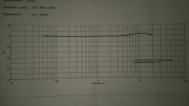
I was on the verge of getting a better microphone, but the idea of having to use 90-200 eur for a DAW before even thinking of the microphone held me back. Now that the DAW is settled, i got a Beyerdynamic MM 1 to try out. It came with an individual frequency response sheet (image), and the good people at Beyerdynamic should send me the frequency response as file soonish. The frequency response of this particular mic doesn't look bad at all, and the mic is designed for measuring purposes. Now I'll just have to figure out how to properly adjust the levels and loopback connection for time alignment with the ASIO drivers.
Also I'll detach the woofers and measure their impedances to see if the woofers' Fs's are converging. The good people at Hifitalo offered to replace the woofers as a measure of good customer service if needed, so I think I'll try that option to get woofers from the same batch, and hopefully of relatively similar Fs and Qt if possible. Of course if the woofers are approaching a similar Fs anyways, I won't put Hifitalo or myself through the trouble.
I was 90 % sure that there had to be something wrong with it, but nope. It works just fine, sounds good (save some crackle when adjusting potentiometers), and provides the needed + 48 V phantom power. It also supports ASIO drivers, which ought to give me a bit better time alignment and thus phase handling, I think. It's a bit vintage, but there's nothing particularly wrong with it, nor is it lacking anything important I could think of.
I was on the verge of getting a better microphone, but the idea of having to use 90-200 eur for a DAW before even thinking of the microphone held me back. Now that the DAW is settled, i got a Beyerdynamic MM 1 to try out. It came with an individual frequency response sheet (image), and the good people at Beyerdynamic should send me the frequency response as file soonish. The frequency response of this particular mic doesn't look bad at all, and the mic is designed for measuring purposes. Now I'll just have to figure out how to properly adjust the levels and loopback connection for time alignment with the ASIO drivers.
Also I'll detach the woofers and measure their impedances to see if the woofers' Fs's are converging. The good people at Hifitalo offered to replace the woofers as a measure of good customer service if needed, so I think I'll try that option to get woofers from the same batch, and hopefully of relatively similar Fs and Qt if possible. Of course if the woofers are approaching a similar Fs anyways, I won't put Hifitalo or myself through the trouble.
Attachments
I just couldn't get the ASIO drivers to work properly, they didn't see left and right output channels, but channels 1 and 2 instead. Channel 1 gave me sound out from left main output, but for some mystical reason I couldn't seem to get any sound from the channel two for timing reference loopback. So, I used Java drivers.
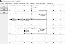
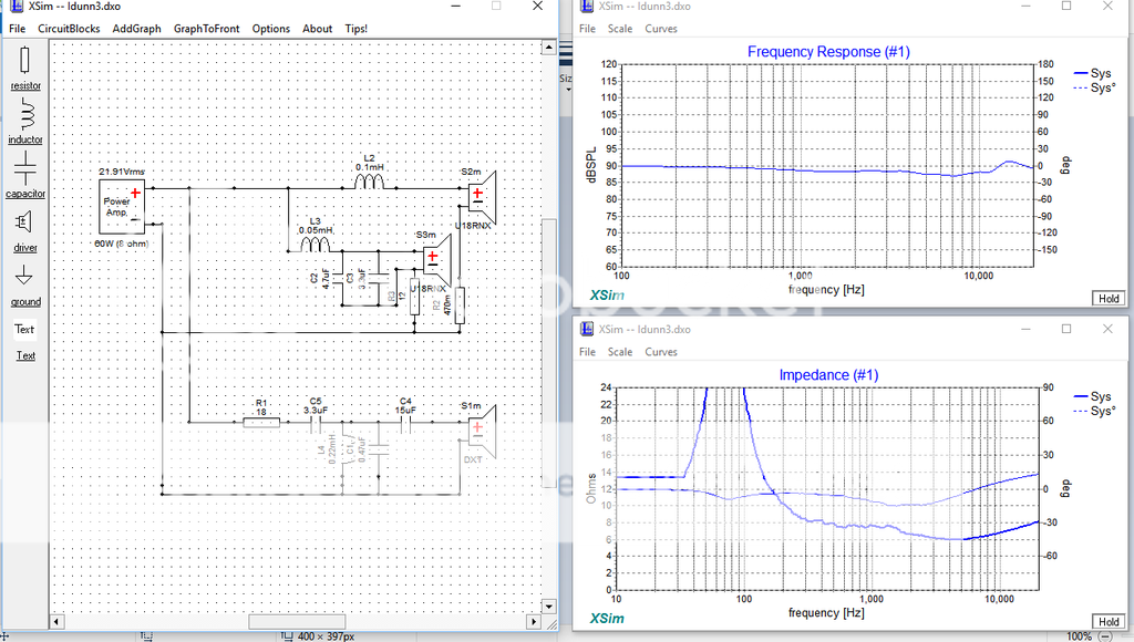
I did a little tweak after first measurements, I changed the resistor after the woofers' parallel capacitor from 1,2 ohms to 2,2 ohms to level a bump at 3,5 kHz a bit. I tried 3,3 ohms also, but that was too much. Right now there just isn't anything more I would like to change in the crossovers. The speakers sound good! Schematic of the current crossover is attached. The "weird" component values are combinations of components I used when I tried to find the right values by ear.
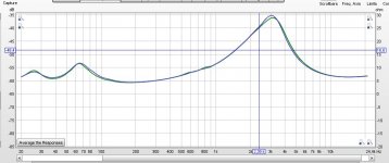
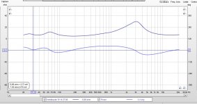
The measurement were made in room, microphone at tweeter height at 1 meter distance from the speaker. The measurement is windowed at about 3 ms. I don't have the calibration file for the mic yet, so the effect of mic response hasn't been removed from the measurement yet. Just by eyeballing the mic's frequency response on paper it's obvious, that the "hill" between 6 kHz and 12 kHz is caused by the mic.
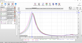
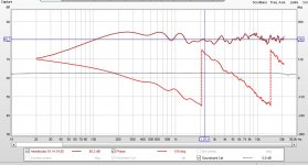
Impedances are pretty constant between left and right speakers. Impedance phase is a bit wonky around cabinet tuning frequency, it doesn't cross zero degrees. The lowest impedance is about 4.2 ohms.
I did a little tweak after first measurements, I changed the resistor after the woofers' parallel capacitor from 1,2 ohms to 2,2 ohms to level a bump at 3,5 kHz a bit. I tried 3,3 ohms also, but that was too much. Right now there just isn't anything more I would like to change in the crossovers. The speakers sound good! Schematic of the current crossover is attached. The "weird" component values are combinations of components I used when I tried to find the right values by ear.
The measurement were made in room, microphone at tweeter height at 1 meter distance from the speaker. The measurement is windowed at about 3 ms. I don't have the calibration file for the mic yet, so the effect of mic response hasn't been removed from the measurement yet. Just by eyeballing the mic's frequency response on paper it's obvious, that the "hill" between 6 kHz and 12 kHz is caused by the mic.
Impedances are pretty constant between left and right speakers. Impedance phase is a bit wonky around cabinet tuning frequency, it doesn't cross zero degrees. The lowest impedance is about 4.2 ohms.
Attachments
Last edited:
The "this is it" moment with the crossover configuration lasted for about six hours, so back to trying different configurations it is.
What I'm yet to get right are sibilants in human voice, spoken (movies etc.) or sung. Also the crossover frequency had slipped too high (almost 4 kHz judging by simulation), which caused a dip in the power response.
It's a shame I can't measure the speakers outside. Measurements in room don't seem to get me too far, for even when windowed they're ragged and dependent of even slight alterations in mic positioning.
The "this is it" moment with the crossover configuration lasted for about six hours, so back to trying different configurations it is.
What I'm yet to get right are sibilants in human voice, spoken (movies etc.) or sung. Also the crossover frequency had slipped too high (almost 4 kHz judging by simulation), which caused a dip in the power response.
It's a shame I can't measure the speakers outside. Measurements in room don't seem to get me too far, for even when windowed they're ragged and dependent of even slight alterations in mic positioning.
Hi there, very much interested in your idunn 2.5 ways project. Can check what is your finalize XO design which works best for your enclosure?
In order to approximate anything resembling real life performance of the idunn 2.5, you should really create appropriate frd and zma files of the drive units. First you trace the FR and IMP curves from datasheet, then process it in a software that adds baffle step, box tuning and calculates minimum phase. After that you can load it to XSim and work on your XO.
In order to approximate anything resembling real life performance of the idunn 2.5, you should really create appropriate frd and zma files of the drive units. First you trace the FR and IMP curves from datasheet, then process it in a software that adds baffle step, box tuning and calculates minimum phase. After that you can load it to XSim and work on your XO.
Second that.
Hello all! Sorry for the long silence, I've been working on two University degrees, LL.M. and B.SC. simultaneously. LL.M. should finally be in the bag. I'm still not quite finished with my design. The bass has a noticeable peak at 80 Hz, which I think is about either room acoustics or the asymmetrical design. I'll try limiting the inner volume to approximately 30 liters (plus effective volume from damping) to make the box symmetrical. Also the tweeter has a nasty sibilant characteristic I'm yet to get rid of. Currently I'd say it's around 7-12 kHz. Luckily I'm starting at a new job that offers more liberal purchasing of hardware. ☺
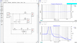
Just to check. Is my impedance graph ok?
What did you use for SPL and impedance graphs to start with? The 0.1 mH inductor for one of the woofers, for instance, looks very strange. Impedance drop to around 1 ohm, however, would be bad for almost any amp. If you want to play around with some drivers, you should get proper graphs for them.
For Seas drivers you can download spec sheets from Seas web page and use SPLCopy (SPL Copy - Speaker Frequency Response Automatic Trace Tool) to get SPL and impedance files for Xsim. Before using the graphs it is wise, though, to compensate for baffle step. You should remove the influence of the baffle used for measurement and add the influence of the baffle you're planning to use. I recall I used Jeff Bagby's Response modeler spreadsheet to do this, but I would still like to find software more suited for removing the influence of one baffle and adding another. Seas provides dimensions for their measurement baffles and boxes on their website.
sunny - no, the caps on the woofers are in the wrong place, that'll kill your amp most likely... better to go L - C -W1 - L - W2 if that makes sense
Hi PeteMck,
Thanks for your kind advise, just to be sure, "L - C - W1 - L - W2 means??
Apology for such noob questions, as i am still in beginner stage.
What did you use for SPL and impedance graphs to start with? The 0.1 mH inductor for one of the woofers, for instance, looks very strange. Impedance drop to around 1 ohm, however, would be bad for almost any amp. If you want to play around with some drivers, you should get proper graphs for them.
For Seas drivers you can download spec sheets from Seas web page and use SPLCopy (SPL Copy - Speaker Frequency Response Automatic Trace Tool) to get SPL and impedance files for Xsim. Before using the graphs it is wise, though, to compensate for baffle step. You should remove the influence of the baffle used for measurement and add the influence of the baffle you're planning to use. I recall I used Jeff Bagby's Response modeler spreadsheet to do this, but I would still like to find software more suited for removing the influence of one baffle and adding another. Seas provides dimensions for their measurement baffles and boxes on their website.
Hi Tsalama,
I had these info in placed alrdy in my xsim alrdy. Had been trying to get the right frequency by meddling with the placement of the components without understanding the importance of the impedance graph. Am lucky to be able to obtain advise from u guys.
- Status
- This old topic is closed. If you want to reopen this topic, contact a moderator using the "Report Post" button.
- Home
- Loudspeakers
- Multi-Way
- Seas "Idunn 2.5"