I labeled this woofer "W1", used hereonout. I'll check the other woofers probably tomorrow and compare, if I can make time from studies and woodwork. Besides the studies in Faculty of Law and Computer Science in the Uni, and this project, I promised I'll paint our old kitchen table's top lemon yellow while my girlfriend is away.  If she'll face the dull worn out pine wood table top on arrival, I can see all kinds of horrible outcomes involving me without my private parts.
If she'll face the dull worn out pine wood table top on arrival, I can see all kinds of horrible outcomes involving me without my private parts. 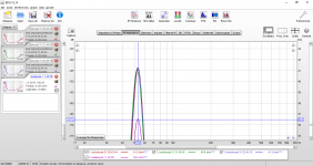
Um, did you let the driver cool off before measuring?
No.
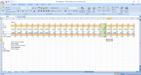
However, the drop in impedance magnitude stayed after a cool off. Here's a measurement after the woofer cooled off the whole night. The red curve (the second from bottom) is from this morning. The Fs is back where it was in the first measurement.
Attachments
i wonder if its a scandinavian thing? t/s parameters are sopposed to be small signal parameters, but scanspeak seems to spec the Fs at more than a couple of volts, but the published impedance curves seem to small signal. pick any ss woofer and you will see the discrepancy in the published impedance peak vs. fs.
best,
Erik
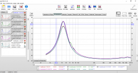
The datasheet for U18 RNX/P features an impedance curve that shows the peak pretty much at specified 43 Hz. The datasheet specs the impedance measurement voltage at 2 V using sine signal.
These measurements I've posted were measured at about 0.2 volts (now that I checked the voltage this morning). I cranked the test rig up as much as possible, which gives me about 0.9 V for sine wave at 1 kHz. At 0.9 V the Fs goes down a tad, from 53 to 52 Hz.
It would be interesting to see if the Fs is closer to spec at 2 V or higher, but sadly my current test rig can't do that. I'll try to beef it up with a power amp..
Attachments
Last edited:
Don't bother yourself with Fs being higher than manufacturer's value.
That's normal in your case and you won't bring it down 10 Hz by
playing test signals. Have the REW calculate full TS parameters
from the 2 curves of which you now have only one. Find some weights
of rubber and place it evenly over the cone to measure the Fs under load.
You can take your weights over to a juwellry store and ask a favor
of measuring it so you know exactly the added mass. You should
have as much weight(range of Mms or more) so the two curves are
frequency wise apart enough to be able to calculate the values.
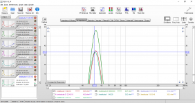
You have some discrepancies in the impedance plots at higher frequencies
(70-85 Hz). Don't use these for calculation. The green curve you have measured
gives Qms=2,71; Qes=0,52; Qts=0,436
edit: Cabinets look sweet.
That's normal in your case and you won't bring it down 10 Hz by
playing test signals. Have the REW calculate full TS parameters
from the 2 curves of which you now have only one. Find some weights
of rubber and place it evenly over the cone to measure the Fs under load.
You can take your weights over to a juwellry store and ask a favor
of measuring it so you know exactly the added mass. You should
have as much weight(range of Mms or more) so the two curves are
frequency wise apart enough to be able to calculate the values.
You have some discrepancies in the impedance plots at higher frequencies
(70-85 Hz). Don't use these for calculation. The green curve you have measured
gives Qms=2,71; Qes=0,52; Qts=0,436
edit: Cabinets look sweet.
Don't bother yourself with Fs being higher than manufacturer's value.
That's normal in your case and you won't bring it down 10 Hz by
playing test signals. Have the REW calculate full TS parameters
from the 2 curves of which you now have only one. Find some weights
of rubber and place it evenly over the cone to measure the Fs under load.
You can take your weights over to a juwellry store and ask a favor
of measuring it so you know exactly the added mass. You should
have as much weight(range of Mms or more) so the two curves are
frequency wise apart enough to be able to calculate the values.
You have some discrepancies in the impedance plots at higher frequencies
(70-85 Hz). Don't use these for calculation. The green curve you have measured
gives Qms=2,71; Qes=0,52; Qts=0,436
edit: Cabinets look sweet.
Since the Fs seems to vary depending on input voltage, I would really like to see if it's close to Seas specs at 2 volts or a bit higher.
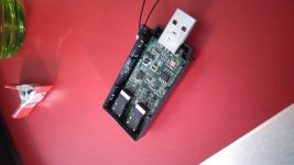
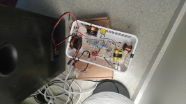
Unfortunately my contraption using a power amp seems to have fried my sound card.
I'm not sure what exactly happened, DC through ground potential difference? That shouldn't cause a current strong enough to cause damage..
A faulty RCA adapter or something else causing the circuit to short? Something I didn't take into account or just plain messed up?
I tried a sine test signal at really low volume, but it didn't work as expected, and I heard some kind of ringing noise around 1000 Hz or so that got softer and louder at times. The usb connected sound card was so hot one could have fried eggs on top of it. The sound card does still produce signal through s/pdif but not analog signal. It also gets really hot even if nothing is connected to it, so hot that I won't try using it anymore.
Well, luckily it was just an Asus that cost 35 euros, so no bankruptcy for me because of that. On the other hand, no impedance measurements for me either until I come up with something else or buy a new sound card.
Unfortunately my contraption using a power amp seems to have fried my sound card.
Try to read ARTA Limp User manual ARTA Download
and next time implement zener diodes to protect the sound card
input from overvoltage. See if you can repair ASUS somehow.
Try to read ARTA Limp User manual ARTA Download
and next time implement zener diodes to protect the sound card
input from overvoltage. See if you can repair ASUS somehow.
Well, quite frankly I have no idea how to repair something like this. I can't even measure any components on this small a raster.
Getting it repaired would probably cost a lot more than the sound card itself. I guess I'll just contact the retailer and tell it malfunctioned while an impedance test. Under the circumstances I doubt they will be too eager to replace it, though.
I'll probably have to just sign it off as one more expense for this project, which I'm intentionally NOT keeping track of.
I'll also check out ARTA and especially the zener diodes, for I don't want to destroy another sound card, let alone my laptop. A nearby electronics retailer seems to have zeners in stock for a hefty price of 0.20 euros/ piece. A bit cheaper than buying a new sound card. Attachments
On the bright side:
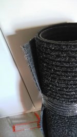
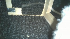
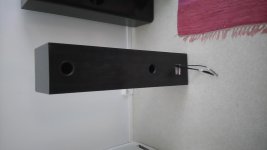
Because I'm not measuring and re-measuring impedances, I had time to seal the cabinets with acrylic seaming paste. I also bought today the carpet I'm going to use for cabinet panel damping. I'll cut and glue it probably tonight.
The carpet weighs 2 kgs/ square meter, which is only half of what the 3 mm thick bitumen roofing felt weighed, but the roofing felts weren't an option because of the sand they contain. I guess the cabinets will look quite funky inside with all that curly fur, though.
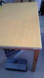
Also: The kitchen table top is now lemon yellow, so my girlfriend won't be pissed because i did "nothing but that speaker stuff".
Second layer of paint is in order tomorrow. Pretty nice these water soluble paints nowadays, basically odor free.
EDIT: the paint looks a bit dull on the picture, but let me tell you, it IS bright lemon yellow in real life. The whole flat bathes in a yellowish hue.
Because I'm not measuring and re-measuring impedances, I had time to seal the cabinets with acrylic seaming paste. I also bought today the carpet I'm going to use for cabinet panel damping. I'll cut and glue it probably tonight.
The carpet weighs 2 kgs/ square meter, which is only half of what the 3 mm thick bitumen roofing felt weighed, but the roofing felts weren't an option because of the sand they contain. I guess the cabinets will look quite funky inside with all that curly fur, though.
Also: The kitchen table top is now lemon yellow, so my girlfriend won't be pissed because i did "nothing but that speaker stuff".
Second layer of paint is in order tomorrow. Pretty nice these water soluble paints nowadays, basically odor free.
EDIT: the paint looks a bit dull on the picture, but let me tell you, it IS bright lemon yellow in real life. The whole flat bathes in a yellowish hue.
Attachments
Last edited:
I've replaced my sound card, but I don't want to try any higher voltage measurements at the moment with that.
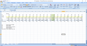
So, I resorted to guesstimating impedances with my cheap multi-meter and a sense resistor in series with the driver. The manufacturer states the multi-meter is reliable at 45-400 Hz, and it's a really cheap one, so the results are to be taken with a grain of salt (or many grains).
I measured the resistance of the sense resistor, voltage from the sense resistor, total voltage with the load (sense resistor+driver) and voltage between speaker cables without any load. Everything free air. The measurements seem consistent enough for some Fs estimation.
At a bit over 6V rms the Fs seems to be where it should, i.e. at 43 Hz. At about 3.8V rms the Fs is at 46 Hz. Still higher than the specified 43Hz at 2V.
I think I'm going with the cabinets I'm making anyways, unmodified. If need be, I can reduce effective cabinet volume later when I get to hear and measure SPL.
Attachments
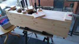
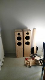
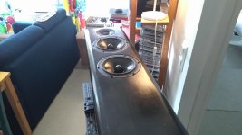
Finally some palpable progress on the project!
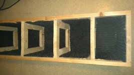
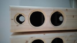
I've done so many frustrating stages of the cabinet manufacturing lately that seem to get me nowhere, that it's not even fun anymore. Measuring, cutting carpet pieces for panel damping, glueing them, measuring more, drilling screw holes, widening the insets to actually fit the drivers etc.
Now, anyways, the baffles are finally attached! I chose to use similar angled irons I used to attach the cabinet panels from the start. The only trouble was that the 20 screws I used to attach the baffles with had to be screwed from inside. So, while the glue set and a freezing wind blew at our balcony, I kneeled and tried to somehow blindly feel the screw holes by hand and reach even the most distant spots, everything through the few openings that the cabinets have. Only one swear word escaped my lips during the whole process though!
Luckily I was using TTAP screws and a compact electronic screwdriver. If I would've used phillips or pozidriv screws or a manual screwdriver, I probably would've just given up.
Now I'll clean up the insets with some padding (one cabinet is done already) and then it's time to do the filleting for both cabinets. After that, it's time to.. https://www.youtube.com/watch?v=O4irXQhgMqg
As a bonus track: some pictures from summery, but at the moment pretty cold Helsinki.
Attachments


Last edited:
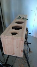
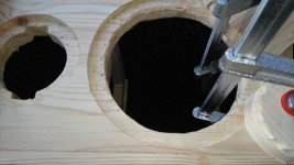
Filleting actually turned out working pretty well! I've been sanding and attending to details pretty much for this whole day. Some padding/filler is applied overnight and I'll sand one more time tomorrow and after that, hopefully, I can paint.
After the paint is done I'll assemble reflex ports with acrylic sealant. I'll also apply a thin layer of the sealant to the driver insets and let them dry some before driver assembly so that I'll get a good seal but won't bond the drivers too firmly, just in case. I'm also going to use sealant strip.
I'll assemble the drivers to the cabinets, fill the cabinets with stuffing and run wires to the terminal holes and seal them for now. I'll assemble crossovers outside the cabinets for now on a breadboard so I can experiment with them.
Now if only I'd hear about the fourth woofer from Hifitalo! They run out of the Seas U18 woofers apparently in the middle of my order. What luck.. I inquired a while ago about the fourth one and they told me they've ordered a batch of 100 U18 woofers from Seas. Hopefully it'll ship soon, for now that the enclosures are actually about to finish after a long process I'm getting pretty impatient to try them out.
Sorry about the images being 90 degrees off. There's something going on with my phone or Android I can't figure out right now. No matter how much I turn them around and replace them in the post they seem to stay on their laps.
After the paint is done I'll assemble reflex ports with acrylic sealant. I'll also apply a thin layer of the sealant to the driver insets and let them dry some before driver assembly so that I'll get a good seal but won't bond the drivers too firmly, just in case.
I'm also going to use sealant strip.I'll assemble the drivers to the cabinets, fill the cabinets with stuffing and run wires to the terminal holes and seal them for now. I'll assemble crossovers outside the cabinets for now on a breadboard so I can experiment with them.
Now if only I'd hear about the fourth woofer from Hifitalo! They run out of the Seas U18 woofers apparently in the middle of my order. What luck.. I inquired a while ago about the fourth one and they told me they've ordered a batch of 100 U18 woofers from Seas. Hopefully it'll ship soon, for now that the enclosures are actually about to finish after a long process I'm getting pretty impatient to try them out.
Sorry about the images being 90 degrees off. There's something going on with my phone or Android I can't figure out right now. No matter how much I turn them around and replace them in the post they seem to stay on their laps.
Attachments
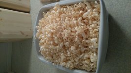
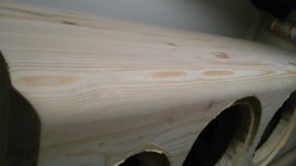
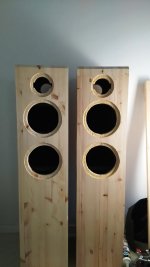
From a distance, it looks like a bowl of pop corn.
Woouldn't it be a shame to cover the wood panels
with a paint? What do you think of wood stain?
A big bowl, the kind that are sold in movie theaters.
I was misleadingly talking about painting, but actually I'm using a dyed lacquer, kind of a combination of stain and lacquer finish. It should leave the grain of wood somewhat visible. I thought about a lighter color that would show the wood more, but all those brown branch spots make them look a bit messy. I saw kitchen chairs made of branchy pine that someone had painted with half opaque white (seemed like similar stain/lacquer kind of paint), and those brown spots looked pretty awful through the white surface.
If I'd bought birch panels I wouldn't have "the branch problem", but I couldn't find them in the dimensions I needed.
Last edited:
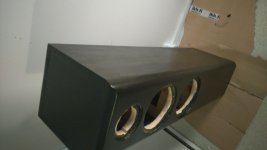
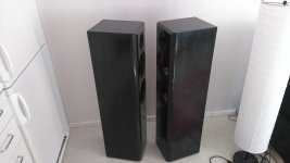
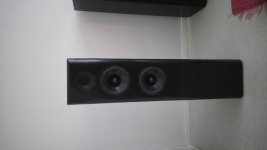
Well, the lacquer finish job didn't really go as I planned. The dye was way too dark for my taste, and even that I had tested it, I went with it anyways. The speakers looked like licorice, which I like to eat, but not as part of interior decoration. We joked with my girlfriend about painting white and pink strips to the sides to make them look like Bassett's Allsorts. The image doesn't really do justice to the licorice feel (the first image).
After sanding, trial and error and mixing the dyed lacquer with clear I ended up with the current finish. I can't say I'm completely happy, but they look pretty nice. A bit like old furniture. However, the lacquer really shows how crude the filleting really is. I hurried on with them, and that shows now. Well, at least there won't be any reasonable doubt if they were actually designed and made by myself.
For some reason I still can't rotate the images to be right side up, not even on my laptop. Sorry about the inconvenience.
After sanding, trial and error and mixing the dyed lacquer with clear I ended up with the current finish. I can't say I'm completely happy, but they look pretty nice. A bit like old furniture.
However, the lacquer really shows how crude the filleting really is. I hurried on with them, and that shows now. Well, at least there won't be any reasonable doubt if they were actually designed and made by myself. For some reason I still can't rotate the images to be right side up, not even on my laptop. Sorry about the inconvenience.
Attachments
What's more exciting for me, at least, is the fact, that I've been able to raw-assemble one speaker, and I'm listening to it right now! Sounds good overall! I also got the word from Hifitalo that the fourth U18RNX/P is on its way to me. I should get it on Monday at the latest.
This time I was wiser to assemble the xo on a breadboard, or, should I say, on a breadbasket. So, easy tinkering as long as I feel that something should be amended. The drivers are assembled with abikos so far, and I'm going to disassemble both of the speakers after initial listening, measure impedances, and solder the driver wires and also add some acrylic sealant to the driver insets, which I'll let half set before the final assembly so that it won't stick to the driver flanges but will seal them properly.
No SPL measurements yet. I'm thinking of refraining of any for some time. Maybe I'll hear what I like without, or run into a situation where I can't tell what I should alter even if I'm not happy. It'll be nice to see what kind of result pleases my ear and then measure, or use measuring to solve a dead end.
Attachments
- Status
- This old topic is closed. If you want to reopen this topic, contact a moderator using the "Report Post" button.
- Home
- Loudspeakers
- Multi-Way
- Seas "Idunn 2.5"