That 0.1 mH coil still looks suspicious to me as to my understanding and experience with these drivers. On the other hand, the circuit before the second woofer isn't like anything I have any experience with. Ultimately, of course, you can assemble the drivers and measure. That will tell what became of it. As a conventional solution, however, you would be looking at 1 mH or so in front of the primary woofer and a lot more in front of the secondary one in a parallel and not cascaded setup. Maybe you could post the raw data you're working with for some more informed feedback.Hi Guys,
What do you all think of this XO layout then? Will this be workable?
Some proper measuring
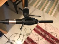
And as for this project of mine goes, I've finally got some proper measuring gear, namely Beyerdynamic MM1 microphone. For some reason BD doesn't make a show out of it, but they provide an individual calibration file for every microphone as long as you ask for it.
I've been toning down the tweeter for a long time, and that shows in my first measurements with the new MM1. My new Denon AVR-X2300W and the calibration function thereof kind of made it apparent to me that any general toning down isn't what I'm after. I'll try to figure out the next step as I finally have a vacation AND a decent measuring mic at hand.
Last edited:
I really don't know why you guys are pursuing this 2.5 project at all! 
You've got the BRAGI MTM modelling. Looks pretty good to me. It won't sound like complete rubbish laid out as MMT either. You get the benefits of low distortion from the dual basses. The tweeter crossed low, you take your chances in the trade-offs of audio game.
A crossover with 0.1mH coils makes no sense at all either. This H1571-08 U18RNX/P is a 0.5mH Le driver judging by the impedance curve. Easy to filter. Good response.
If you are interested in impedance and (say 4dB) bafflestep correction by other means, you do it this way: mh-audio.nl - Home
Why reinvent the wheel?
I really don't know why you guys are pursuing this 2.5 project at all!
Why reinvent the wheel?
Isn't that kind of the fun part of this hobby?
But yeah, if someone is considering a two woofer setup with these drivers, I'd say go with Bragi. I haven't heard Bragi though, just seen the Seas measurements. And as said, I wasn't aware of the Bragi design at all when I started pursuing this project. If I were, I'd probably built Bragi in the first place, or at least laid the drivers out as MTM because MTM would work fine with 2.5 as well, and that would've left open the option of reverting to Bragi when I'd gotten enough of dabbling with my designs. I might just try Bragi XO with this setup as well. Not yet, though, for I finally have a proper measuring mic.
Last edited:
Hi Guys,
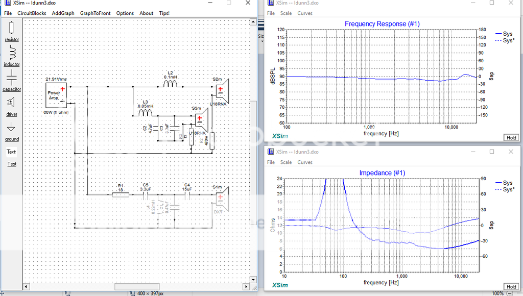
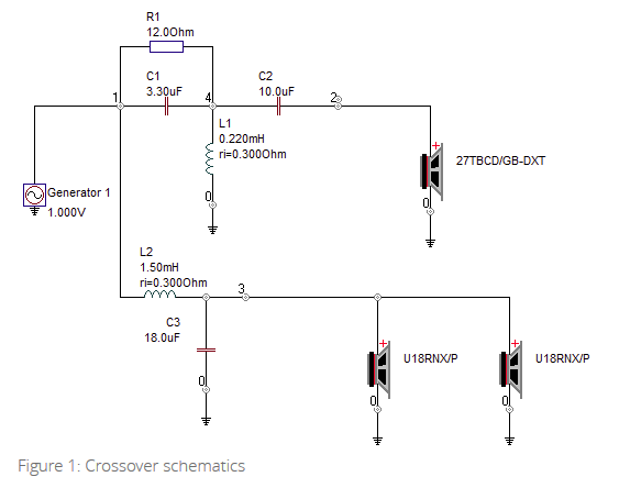
What do you all think of this XO layout then? Will this be workable?
Answering the post #100, judge for yourself if that is satisfactory for you.
Drivers are all calculated in, two of U 18 RNX and DXT.
Attachments
Answering the post #100, judge for yourself if that is satisfactory for you.
Drivers are all calculated in, two of U 18 RNX and DXT.
I took a stab at well with my data.
Attachments
My data doesn't seem to work too well (boy is it easier to do this with a mic one can actually trust!).
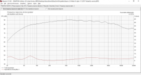
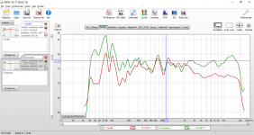
The current version as planned and as measured. Measurement 1/6 octave smoothed, no gating.
Edit: got the XO wrong the first time, amended.
The current version as planned and as measured. Measurement 1/6 octave smoothed, no gating.
Edit: got the XO wrong the first time, amended.
Attachments

Last edited:
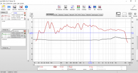
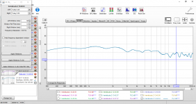
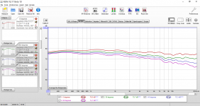
The Audyssey EQ that calibrates the Denon amp with an enclosed mic seems pretty decent though, if a bit bass heavy. No gating, but 1/6 smoothing to show in-room response of bass as well. I included also an image of the hero of the day.
Attachments
Last edited:
I think Lojzek is saying post #100 crossover isn't very good...
Having paid attention to quite a few 6" projects, I notice the H1456-08 ER18RNX, H1571-08 U18RNX/P, Paper Peerless 830875 and polycone Peerless 830874 are all pretty similar.
All around 1mH inductance from the impedance curve, despite the damping rings. All around 6 ohms DC. The polycones have less cone resonance around 4-4.5kHz, as you'd expect. Notching that resonance is what MarkK did in his famous design with an LCR shunt, and it certainly helps phase, but I'm not convinced you actually hear it too much.
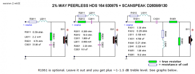
Troels' Nomex 164 is one way to do a 2.5: PEERLESS-NOMEX-164
I like this Michael Chua design for the ER18RNX and H1189-06 27TDFC. It uses impedance correction: Seas ER18RNX with 27TDFC
The exact calculation is here, and I think about 4dB BSC and 7.5R/15uF Zobel would be about right: mh-audio.nl - Home.
You have the H1147-06 27TBC/G which is about 1dB louder.
But all very adjustable IMO. And converting that to MTM, or MMT which is much the same thing on linkwitz-riley filters, would be dead easy.
Having paid attention to quite a few 6" projects, I notice the H1456-08 ER18RNX, H1571-08 U18RNX/P, Paper Peerless 830875 and polycone Peerless 830874 are all pretty similar.
All around 1mH inductance from the impedance curve, despite the damping rings. All around 6 ohms DC. The polycones have less cone resonance around 4-4.5kHz, as you'd expect. Notching that resonance is what MarkK did in his famous design with an LCR shunt, and it certainly helps phase, but I'm not convinced you actually hear it too much.
Troels' Nomex 164 is one way to do a 2.5: PEERLESS-NOMEX-164
I like this Michael Chua design for the ER18RNX and H1189-06 27TDFC. It uses impedance correction: Seas ER18RNX with 27TDFC
The exact calculation is here, and I think about 4dB BSC and 7.5R/15uF Zobel would be about right: mh-audio.nl - Home.
You have the H1147-06 27TBC/G which is about 1dB louder.
But all very adjustable IMO. And converting that to MTM, or MMT which is much the same thing on linkwitz-riley filters, would be dead easy.
Last edited:
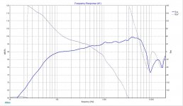
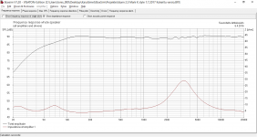
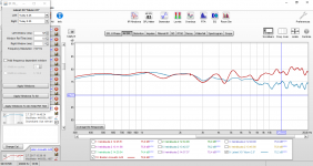
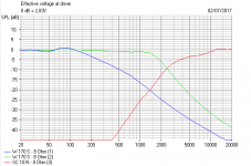
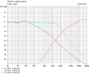
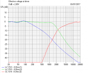
A measurement of the current version. I'm quite happy with this one so far. I tried adding 2 dB or so to the top end which is rolling off, but anything above the current level tends to make them sound a bit thin and harsh. I guess it's because of the wave guides that reduce directivity at the top octave and, thus, the top octave power response is higher than it would be with a "conventional" tweeter.
The measurement is shown with 2 ms gating, 300 - 20000 Hz, no smoothing. The current XO is included as well.
The measurement is shown with 2 ms gating, 300 - 20000 Hz, no smoothing. The current XO is included as well.
Attachments

Yes, I figured that.I think Lojzek is saying post #100 crossover isn't very good...
By "taking a stab" I meant that I tried the post #100 crossover with my data, not that I tried to make a better version of it. It didn't look too good with my data either, and after posting the simulation curve, I found out by my measurements that my tweeter level in BoxSim was about 4 dB too high. You can eyeball 4 db off from the top end of my curve depicting the post #100 crossover design for a bit more realism.The polycones have less cone resonance around 4-4.5kHz, as you'd expect. Notching that resonance is what MarkK did in his famous design with an LCR shunt, and it certainly helps phase, but I'm not convinced you actually hear it too much.
MarkK notched the woofer at its resonance peak which isn't a problem with these polycones, as you pointed out. However, he controlled the tweeter with notch filters as well. If you take a look at Seas's measurement of Idunn, you'll notice that it blooms quite a bit around 7 kHz and at the top octave, whereas at 4 kHz - 6 kHz it's sagging a bit. MarkK kind of reversed that setting, leveling 2 kHz - 10 kHz region nicely and reducing the top octave level a bit from overall level, and I think that approach works pretty well with the DXT tweeter.
TSalama, last time someone came up with a MarkK type ER18RNX design, which was new to me at the time, I asked them where they had got such ridiculous and overcomplicated ideas from! The only thing I liked was the 4.5kHz notch on the bass. It all got a bit embarrassing when MarkK himself rocked up to justify it. But I still think the design sucks.
This reeks of noobiness to me. Badly laid out, no preferred values, TWO notches on the tweeter that do little beyond reducing level 4dB above 5kHz. Poor impedance curve. You haven't built this have you? Where you gonna buy those value components? I've laid it out more conventionally below.
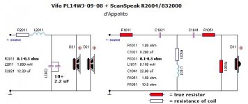
Here's a couple of standardish Troels' layouts. The MTM is quite good, IMO. But I'd lift the BRAGI tweeter filter, and tailor the bass/mid end to fit that as a start. Can't be hard even with a bassy 2.5 plan. And 2.5 is bassy, because you get the full 6dB bafflestep.
This reeks of noobiness to me. Badly laid out, no preferred values, TWO notches on the tweeter that do little beyond reducing level 4dB above 5kHz. Poor impedance curve. You haven't built this have you? Where you gonna buy those value components? I've laid it out more conventionally below.
Here's a couple of standardish Troels' layouts. The MTM is quite good, IMO. But I'd lift the BRAGI tweeter filter, and tailor the bass/mid end to fit that as a start. Can't be hard even with a bassy 2.5 plan. And 2.5 is bassy, because you get the full 6dB bafflestep.
Attachments

This reeks of noobiness to me. Badly laid out, no preferred values, TWO notches on the tweeter that do little beyond reducing level 4dB above 5kHz. Poor impedance curve. You haven't built this have you? Where you gonna buy those value components? I've laid it out more conventionally below.
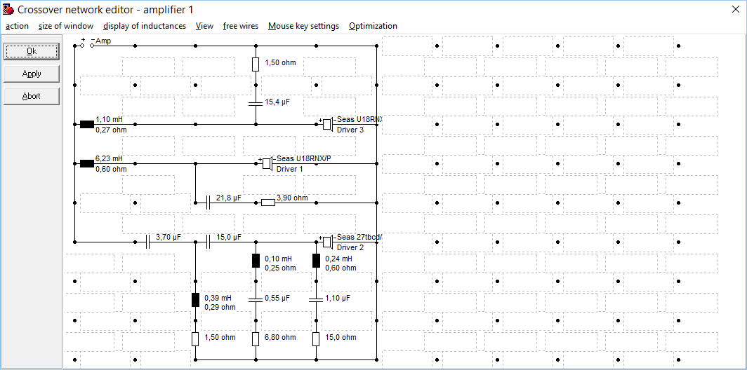
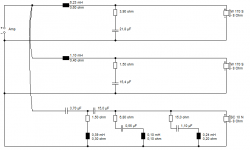
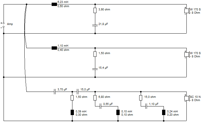
Those are asbuilt component values, or aggregates thereof, to be precise. Once I've reached the crossover design I intend to keep, I'll order the parts I need with values close enough. I find no point in stacking up with heaps of expensive capacitors, for instance, but i combine what i have at hand, as I gradually adjust the crossover. That's the reason for odd looking values: they're sums of two or more components. Inserting all of the individual component values to the crossover design would just make it messy. Therefore I use calculated aggregate values instead.
This is the crossover used in the measurements I've posted today.
Edit: The 6.23 mH inductor isn't actually an aggregate, but the result of adding enameled copper wire to an inductor, measuring and adjusting the inductors to be of even inductance for both crossovers. Once I ended up with 6.23 mH in both inductors, I saw no point in going through the trouble of adjusting both of the inductors again just to end up with a prittier value.
Last edited:
I'm enjoying this. You are making me think.
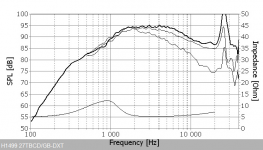
AFAIK, what shallow waveguides do to tweeters is greatly boost output around 3kHz. Less effect at the top end. Enter the H1499-06 27TBCD/GB-DXT.
Looking at that, you'd think we need to boost the very top end above, say, 7kHz. Your filter does that electrically. But a tweeter curve like that is not unusual with much simpler components IMO. I must model the Bragi tweeter filter. It must do something similar. I also like, say, a 7.5R/0.68uF Zobel on metal tweeters to tame the top end and improve impedance, so must try that.
Attachments
OMG! Who can spot the weirdness in this official SEAS Bragi filter?
Clue: It's the 12R resistor connected to ground via a small 0.22mH coil...
But it does the right thing to the electrical response...here I've compared it to your double notch tweeter circuit.
Clue: It's the 12R resistor connected to ground via a small 0.22mH coil...
But it does the right thing to the electrical response...here I've compared it to your double notch tweeter circuit.
Attachments
OMG! Who can spot the weirdness in this official SEAS Bragi filter?
Clue: It's the 12R resistor connected to ground via a small 0.22mH coil...
But it does the right thing to the electrical response...here I've compared it to your double notch tweeter circuit.
Yeah, it's peculiar.
It also shifts tweeter phase at under 2.5 kHz or so, and the phase doesn't align too well with my woofer setup. It works in the Bragi crossover, but would take some adjusting of my woofer crossover section. I saw it as a potential option for my tweeter section and played around with it a while ago in Boxsim.Hmm... you're not going to like this.
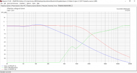
I did a few things with the weird official SEAS Bragi filter, and got quite close with a conventional filter. But here's what I got with your complicated filter.
Most of it can go. A single 3.3R replaces two notches and the 1.5R. Electrical comparison below.
I did a few things with the weird official SEAS Bragi filter, and got quite close with a conventional filter. But here's what I got with your complicated filter.
Most of it can go. A single 3.3R replaces two notches and the 1.5R. Electrical comparison below.
Attachments
Hmm... you're not going to like this.
Most of it can go. A single 3.3R replaces two notches and the 1.5R. Electrical comparison below.
I would actually like it if i could get rid of most of the clutter from the tweeter section. It's hard to fit all of it on a board small enough to fit through a woofer inlet into the cabinet eventually.
The single resistor is somewhat in the ballpark, but in my books this isn't the same. In fact, there are several differences of multiple dBs when I model it in Boxsim. The single resistor is the dashed line in the image.
Attachments
- Status
- This old topic is closed. If you want to reopen this topic, contact a moderator using the "Report Post" button.
- Home
- Loudspeakers
- Multi-Way
- Seas "Idunn 2.5"