Well, by halving longest dimension, the lowest mode is eliminated. But with an oblique wall, all vertical modes will also be attenuated a lot. Look at attachment, simulation does not allow oblique walls.
-
Dividing the caginet of a floorstande is not my idea, but it is not common practise either. PSB does that Imagine X2T Tower - PSB Speakers
"Extended Bass Response that's Fast and Articulate
Each 6 1/2" woofer has its own separate acoustic chamber tuned with a front-facing port to achieve incredible control and spatial, dynamic sound quality. Dividing and individually porting the chamber eliminates standing waves inside the X2T's tall, slim speaker cabinet. The placement of the woofers in multiple positions also reduces the first reflection phenomenon, minimizing the negative effects of the primary ‘floor bounce' reflections, creating a much more accurate and tuneful bass performance. The result being low distortion bass response that speaks with powerful authority."
An externally hosted image should be here but it was not working when we last tested it.
Attachments
Last edited:
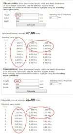
The inner dimensions should be something like this. I added the holed braces (one for each compartment) I was earlier talking about .
The "drivers" (circles protruding from front) are of course just mocking driver placement in the image. In reality there's going to be the baffle between the inner volume and those drivers. The holes in the baffle for woofers will be 146 mm in diameter, naturally not the 176 mm which is the woofers' outer diameter. Same thing with the tweeter.
I also got the reflex ports a bit wrong in the image: port length 141 mm starts from the outer surface of the back panel, not from the inner surface of course. So the ports will protrude 123 mm (141 mm-18 mm) into the enclosure, not 141 mm.
Brace placement I did pretty randomly just to mock them out. The essential thing in the inner dimensions is of course the divider placement to get volumes for both compartments right. The overall inner height used here, 878 mm, is somewhat smaller than the total inner height of the box, 964 mm, so I'll have to add something at the bottom of the box to reduce total volume. I might just be able to fit a separate little chamber at the bottom for XO.
The brace placement I'll have to consider better later, for there might be possible benefits for box mode reducing. Brace and port volumes I subtracted from inner box volume when calculating the dimensions.
Thank you Lojzek for the BBC paper! I'll read it through in a couple of days after we've moved and I've got some school stuff done. I've also got The Loudspeaker Design Cookbook by Vance Dickason waiting for me at my local library.
")
Last edited:
You're welcome. Have a look at Troels Gravesen's Ekta Grande.
Maybe this will help you get an idea of how things could be done
better in regard to placing braces. Your slanted divider looks as
wrong as hell to me. Will you be able to put stuffing to the wall
of the divider close to the driver?
Ekta-Grande
Maybe this will help you get an idea of how things could be done
better in regard to placing braces. Your slanted divider looks as
wrong as hell to me. Will you be able to put stuffing to the wall
of the divider close to the driver?
Ekta-Grande
Some speakers with asymmetric inner dimensions and shape
About Coincident Speaker Technology
Speakers
Sonja? Gallery - YG Acoustics
Of course one divider is not enough for cabinet support. And also damping material should be used to attenuate standing waves. There are two problems to cope with - internal standing waves and panel vibrations.
About Coincident Speaker Technology
Speakers
Sonja? Gallery - YG Acoustics
Of course one divider is not enough for cabinet support. And also damping material should be used to attenuate standing waves. There are two problems to cope with - internal standing waves and panel vibrations.
A busy week! We packed our things and moved to our new flat. There's still some cleaning and stuff like that to do, and on top of that I have lots to do at school as well. I'm hoping to make time to read the BBC paper and skim any cabinet design parts of the Dickeson too this week.
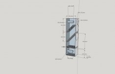
I had time to test the lower woofer dimensions on the sketchup, and it's clear now that the slanted divider won't work as is. There's just too little room behind the lower woofer, the magnet will be practically touching the divider (image 1).
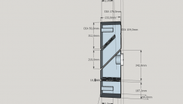
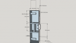
I made a rude sketch (not calculated dimensions, and the sketch is also missing braces) of another idea the enclosure could be divided and have both woofers close to each other (image 2). Because the lower woofer is still at play at ~1000 Hz I would have lobing issues if they're farther apart.
On the other hand, if I placed the lower woofer clearly lower than the upper one, that might help with Allen effect at around 140 Hz where the classical floor reflection dip appears..
I'm also seriously starting to consider just making one compartment at 45 liters or so for both woofers.
At any case, I'll be using at least two braces in addition to the possible divider, and also filling in the cabinet and maybe some damping for cabinet panels.
I had time to test the lower woofer dimensions on the sketchup, and it's clear now that the slanted divider won't work as is.
There's just too little room behind the lower woofer, the magnet will be practically touching the divider (image 1).I made a rude sketch (not calculated dimensions, and the sketch is also missing braces) of another idea the enclosure could be divided and have both woofers close to each other (image 2). Because the lower woofer is still at play at ~1000 Hz I would have lobing issues if they're farther apart.
On the other hand, if I placed the lower woofer clearly lower than the upper one, that might help with Allen effect at around 140 Hz where the classical floor reflection dip appears..
I'm also seriously starting to consider just making one compartment at 45 liters or so for both woofers.
At any case, I'll be using at least two braces in addition to the possible divider, and also filling in the cabinet and maybe some damping for cabinet panels.
Attachments
Some updates on the project:
The panels should arrive tomorrow so I can get to cutting the ones I have to.
For the box design, I think I'll just put both woofers in the same chamber. Zaph's results posted in this thread (http://www.diyaudio.com/forums/mult...oofers-one-cabinet-two-separate-chambers.html) convinced me the divider isn't necessary.
I'll use two or three horizontal braces. Probably three. I'll just have to buy one more panel to cut braces from.
I think I'll use two 50 mm dia/ 143 mm long slanted reflex ports, for I can get slanted ports that fit my volume/tuning nicely and together give a low air flow speed: http://en.uraltone.com/cabinet-and-case-hardware/bass-reflex-tubes/bassorefleksiputki-intertechnik-50mm-sisahalkaisijalla-pituus-143mm.html
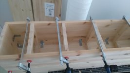
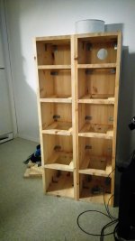
The first cabinet is in the making. I chose to go with four horizontal holed braces. Some of the panels were flawed, so I'll have to wait for the vendor to replace them before I can glue the second cabinet.
Attachments
Last edited:
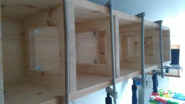
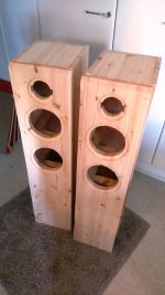
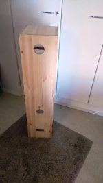
Both cabinets have been made, although without baffles yet. Reflex ports and terminals have been bought. I'll make tomorrow holes for ports and terminals at back panels and hopefully manage to complete most of the baffle holes and flush mounting insets for drivers. I'll also have to visit a hardware store to get some bitumen roofing felt for damping.
The tweeters and 3 woofers are on their way. I'll have to wait for the fourth woofer a bit, for the supplier currently only had three of them in stock. Also inductors, some metal oxide resistors, speaker cable etc. are in the same delivery. I'll get capacitors later from a nearby diy store, for they have good prices for capacitors (Intertechnik, JB, Icel and such) and I can just pop in whenever I need something.
The tweeters and 3 woofers are on their way. I'll have to wait for the fourth woofer a bit, for the supplier currently only had three of them in stock. Also inductors, some metal oxide resistors, speaker cable etc. are in the same delivery. I'll get capacitors later from a nearby diy store, for they have good prices for capacitors (Intertechnik, JB, Icel and such) and I can just pop in whenever I need something.
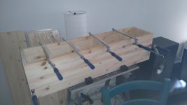
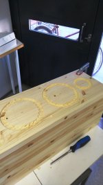
I've rough cut all openings to the cabinets. The insets for flush mounting were a pain in the proverbial to make with a forstner bit and a chisel! I've still got a lot of finishing work and fixing with putty to do.
I also faceted the upper edge of the baffles, for I gathered they cannot be easily filleted with hand tools. Sides are yet to be filleted.
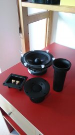
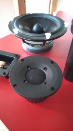
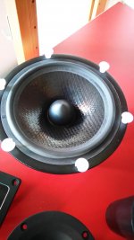
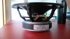
The drivers are here, save the fourth woofer, no word on that yet. I'm pretty impressed by the look and feel of them! I'll post impedance curves for the drivers soonish. It's interesting to see how close the woofers' Fs's are to each other and to the specs. The images also feature the reflex ports and speaker terminals I decided to buy.
I've been struggling a bit finding the damping material for cabinet panels. The dedicated damping sheets (for car doors etc) would be an obvious choice, but judging by their price they're probably made of gold, diamonds and stuff like that. I've also ordered two kind of roofing felts, but they seem to be flaking sand or some other little particles that would be OK on a roof, but not in a speaker cabinet together with moving mechanical parts of rather fine tolerances. I fiddled yesterday a carpeting material for balconies and patios featuring a rather heavy rubber base and grey curly fur on top. I think I'll go with that, the fur'll keep filling nicely in place as well. I' can just send the roofing felts back and be fully compensated.
I also faceted the upper edge of the baffles, for I gathered they cannot be easily filleted with hand tools. Sides are yet to be filleted.
The drivers are here, save the fourth woofer, no word on that yet. I'm pretty impressed by the look and feel of them! I'll post impedance curves for the drivers soonish. It's interesting to see how close the woofers' Fs's are to each other and to the specs. The images also feature the reflex ports and speaker terminals I decided to buy.
I've been struggling a bit finding the damping material for cabinet panels. The dedicated damping sheets (for car doors etc) would be an obvious choice, but judging by their price they're probably made of gold, diamonds and stuff like that. I've also ordered two kind of roofing felts, but they seem to be flaking sand or some other little particles that would be OK on a roof, but not in a speaker cabinet together with moving mechanical parts of rather fine tolerances. I fiddled yesterday a carpeting material for balconies and patios featuring a rather heavy rubber base and grey curly fur on top. I think I'll go with that, the fur'll keep filling nicely in place as well. I' can just send the roofing felts back and be fully compensated.
Attachments
-
 Kaapit sisältä.jpg430.2 KB · Views: 221
 -
 Etulevyjen mallaus.jpg285.8 KB · Views: 178
 -
 Takareiät.jpg191.7 KB · Views: 172
 -
 Upotukset.jpg331.6 KB · Views: 169
 -
 Kaikki osat.jpg218 KB · Views: 164
 -
 Puolilähikuva.jpg209.3 KB · Views: 71
 -
 Bassoelementti ylhäältä.jpg262.8 KB · Views: 70
 -
 Bassoelementti sivusta.jpg483.2 KB · Views: 78
Last edited:
For a price effective option for damping, I use Home Depots door/window 12" wide sealer sheets. They are peel and stick, cut with a razor knife and are flexible for getting in corners and smoothing. Also can be stuck on top of each other if you find you need more in some spots. I think it's about $20 for 10 foot roll but comes in larger quantities too.
Cabinets are looking good and that woofer is darn sexy.
Sent from my iPhone using Tapatalk
Cabinets are looking good and that woofer is darn sexy.
Sent from my iPhone using Tapatalk
For a price effective option for damping, I use Home Depots door/window 12" wide sealer sheets. They are peel and stick, cut with a razor knife and are flexible for getting in corners and smoothing. Also can be stuck on top of each other if you find you need more in some spots. I think it's about $20 for 10 foot roll but comes in larger quantities too.
Cabinets are looking good and that woofer is darn sexy.
Sent from my iPhone using Tapatalk
Thank you for the hint! Sadly, no Home Depots in this corner of the world.
I still should probably check sealer strips and sheets etc as a possibility. I haven't run across any sealer sheets here though, the only thing I can find are relatively narrow sealer strips, but in the quantity they would cost a lot more than any other option.That woofer IS sexy, and IMHO that tweeter too.
i wonder if its a scandinavian thing? t/s parameters are sopposed to be small signal parameters, but scanspeak seems to spec the Fs at more than a couple of volts, but the published impedance curves seem to small signal. pick any ss woofer and you will see the discrepancy in the published impedance peak vs. fs.
best,
Erik
best,
Erik
i wonder if its a scandinavian thing? t/s parameters are sopposed to be small signal parameters, but scanspeak seems to spec the Fs at more than a couple of volts, but the published impedance curves seem to small signal. pick any ss woofer and you will see the discrepancy in the published impedance peak vs. fs.
best,
Erik
I hope the engineers from a neighboring country will prove trustworthy and the Fs won't be too much off! I'd say "neighboring Scandinavian country", but geographically Finland isn't a part of the Scandinavian peninsula, although usually affiliated (and I affiliate myself) to the Scandinavian countries. That of course means that I'll blame "the bloody Scandinavians" if the drivers will be off.
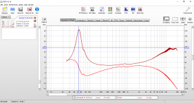
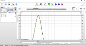
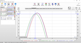
A little audio signal seems to be doing something, the Fs is creeping a bit down. I'll see and post if I can provoke any further change in the Fs in a few days term. Otherwise I'll have to see if I'll have to make any changes to the cabinet volume while I still can.
Attachments
Last edited:
Is this free-air measurement or installed in cabin? Usually free-air is higher freq. Bass tuning is not so picky as you think, so I have read!
What are the pro's and cons of tuning below FS? - Techtalk Speaker Building, Audio, Video Discussion Forum
What are the pro's and cons of tuning below FS? - Techtalk Speaker Building, Audio, Video Discussion Forum
Is this free-air measurement or installed in cabin? Usually free-air is higher freq. Bass tuning is not so picky as you think, so I have read!
What are the pro's and cons of tuning below FS? - Techtalk Speaker Building, Audio, Video Discussion Forum
Both of the measurements are free air, woofer standing on a table on its magnet, wires attached.
The tuning is already under the Fs (38 Hz tuning for 43 Hz specified Fs), but if the Fs stays above 50 Hz or so, I'll have to rethink the cabinet volume. Some of the other T/S parameters are such a pain to measure that I don't know if I'll calculate/measure any new T/S parameters for the woofers. For what I've reckoned playing around WinISD, UniBox and BoxSim and my current speakers in real life, a few liters and Hz won't make or break anything, just change the overall balance somewhat.
Last edited:
i dont think they are lying so much as used to different measurement conventions. if they wanted to lie they would alter the z data to match.
i typically go by the madiaound recommendations as a starting point. you can also examine the Klang Tong Nada kit. i think thatin use, the specs will prove closer that we would guess.
best,
erik
i typically go by the madiaound recommendations as a starting point. you can also examine the Klang Tong Nada kit. i think thatin use, the specs will prove closer that we would guess.
best,
erik
- Status
- This old topic is closed. If you want to reopen this topic, contact a moderator using the "Report Post" button.
- Home
- Loudspeakers
- Multi-Way
- Seas "Idunn 2.5"