... i changed them from the class D to the AB, oh boy, instead of a 12db slope down at 8Khz i get a major peak at 13khz that drops to normal level around 18Khz. any clue on why its not woring on my class D ? the other transformer did not seem to care much about the amplifier.
Back in post#18 you said that the AB & D amps measured the same.
What transformers were used for those measurements? I thought all the HolmImpulse measurements were made with the toroids.
Adding a 1 - 2 ohm resistor in series with the primary should tame the peak with the AB amp.
sandwich-esl-yummie Post #18
You have a system with 3 parts that each have an inherent transfer function, the amplifier, transformer, and ESL panel. However, the impedance of the ESL can affect the transfer function of the transformer. Similarly, the impedance seen by the amplifier can effect its response; although this is more common with class-D than class-AB amps.
The only way to truly know what is going in is to make 3 measurements:
1) measure voltage response at transformer primary
2) measure voltage response at transformer secondary
3) measure SPL response 1m from ESL panel
Peaks and roll-offs can come from any of these three. Often a peak in one counteracts a roll-off in another.
Measuring just SPL there is no way to know.
You can measure 1) & 2) fairly easily using a voltage divider and a bit of care to keep the volume low when measuring.
One scenario that would fit your description is a transformer with inherent peaking in top octave:
- measurement 1) is flat for AB and rolled off for D when using the toroids.
- measurement 2) then shows a peak with AB, but D looks more flat before the roll-off, resulting from combining 1) with inherent transformer response.
Thx bolsert!,
all measurements of the panels where made with a custom transformer with a C core with a step up ratio of 1:120. so all plots on all the post about the measurements of the panels are correct and made with this transformer, indeed i did not see any difference between the class D and the AB on that transformer.
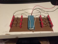
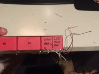
i ordered these small terroids 6 volt duo sec and 220 prim, 25VA so not incredible big but, should work fine for high frequencys because everyone used those 50VA 6 volt terroids, these i just ordered with the pcb material since they where only 9 euro a piece, a steal i think. (thats 1/3 there normal price in any other shop) so i had high hopes, and tried them a week back and ended up with this rolloff at 8 khz so i disconnected them and went on with the panel on the old transformer. today i thought i might give it a second shot, maybe i did something wrong")
i try and make those 3 measurements maybe next week, would be nicie to know if these teroids could be used, saves some money and then they are not bought to be on the shelve
all measurements of the panels where made with a custom transformer with a C core with a step up ratio of 1:120. so all plots on all the post about the measurements of the panels are correct and made with this transformer, indeed i did not see any difference between the class D and the AB on that transformer.
i ordered these small terroids 6 volt duo sec and 220 prim, 25VA so not incredible big but, should work fine for high frequencys because everyone used those 50VA 6 volt terroids, these i just ordered with the pcb material since they where only 9 euro a piece, a steal i think. (thats 1/3 there normal price in any other shop) so i had high hopes, and tried them a week back and ended up with this rolloff at 8 khz so i disconnected them and went on with the panel on the old transformer. today i thought i might give it a second shot, maybe i did something wrong
i try and make those 3 measurements maybe next week, would be nicie to know if these teroids could be used, saves some money
and then they are not bought to be on the shelve This thread continues from my second tread i started... sorry http://www.diyaudio.com/forums/planars-exotics/282787-stacked-esl-v4.html
Sooo back to my thread. sorry for the double thread, i beter should continue here. so people can read the whole story if someone wants to try the same or wants to contribute some knowledge.
I played with the mesh this weekend and , well i am not sure yet. i somehow find it a bit complicated. making spacers glueing mesh to it, making copper connections etc... maybe ill wrap it up and put it in a bag for later use. well hell it was only 140 euro's in total.......
ok enough bitching from my part. mesh works, and i am pretty sure it could be used for bigger stat panels (since i cant use a support structure inside the esl)with a proper backing like egg crate, sort of like Gerald did. except that this mesh (and i did not tell that yet) is based on a polyester fabric with a layer of copper and zinc against corrosion. so you can etch it!. i tried several pieces and it works in just normal acid used for copper etching. so if you want to make a stat with openen of 50% (minus the structure to support it) you can still segment it if you want. the fabric looks almost transparent witch is cool.
But for my project i did not get the things i wanted. going really small hole sizes did not do much in terms of efficiency.and the high roll off remained. but not all is wasted money. I did discover the roll off that changed frequency when stacks added is due membrane weight and not the amount of stacks nor the capacitance increase.
there is still A roll off starting at 15 khz, this might be my
amp
sound card
transformer
or mic
although the last should be calibrated but i doubt to what extend. the sound card i remember i measured once few years ago (lost calibration file of course) and was pretty straight line frequency wise. at least not this big hump.
maybe there is someone from the Netherlands where i can calibrate my mic against a good mic ? so i at least have a better feeling
The mesh still might be usable in a very tiny version for tweeter use. where it does not have to span much distance. low dc spacings and very thin stator makes it able to stack 6 of those before rollof starts at 18-20khz. but i need 1 micron mylar for that so it has to wait
i might go back to the drawing bord for the PCB stators. i thought of a way to drill multiple panels at once to decrease drilling time. not tested yet so first i go small or make a little test. before i ruin multiple stators at once
Things i will take into acount for this version is
1. Bolsert suggested smaller holes so i go to 1mm isntead of 2
2. Bolsert suggested more open area. so i go 46.3 %
3. i failed to use triangular pitch on the latest stator design witch hurts stiffness. so will be using that.
4. according to tests i need thinner foil. so if my 1 micron comes in time ill be using that!
5. i will make some spacers with membranes attached that i can swap out.
A few with the new 1 micron foil, a few with 3 micron foil. and see what happens when stacked.
Oh one last thing and maybe Bolsert knows. do you know if the static force of the middle membrane of a 3 stacked esl might be pulling on the ones on the outer sides ? since its opposite charged, i was wondering about that when i decreased the size of all spacers. or gets this force blocked by the next stator ?
one last question anyone has a super mega good idea to increase membrane stability ? without going higer in resonance ? i tried dots but did not had a feeling it worked at all. it is quite often that i hear membranes are not pulled into a stator but still hear verry faint sizling. you can hear this noise as well when you power up an ESL63 although in perfectly fine working order.
Last edited:
hmm noticed why they siszle . looks like my HV cascade of the - high voltage and the + high voltage are not equal. first of all since i had double caps in the + version for the use with the EAP speaker. my negative version cant handle the same voltage . another thing is that the caps are working near there voltage limit so going over it will end up in sparks inside my caps... do this enough and gone it is.. so i might need to make new ones with higher voltage caps, since they are fed by an inverter starting voltage can reach 800 volt before the multiplier. i feed them from one inverter. if i wanted a really balanced system i could go for 2 inverters.
i test the membranes one by one and i noticed that the + HV ones collapsed into the menbrame way sooner then the - membranes. so a difference in voltage there(i could not even collapse the - before the capacitors starts sparking). another thing i recon is stacking in powers of 2. to have all things equal loaded each HV lader the same load.
. another thing is that the caps are working near there voltage limit so going over it will end up in sparks inside my caps... do this enough and gone it is.. so i might need to make new ones with higher voltage caps, since they are fed by an inverter starting voltage can reach 800 volt before the multiplier. i feed them from one inverter. if i wanted a really balanced system i could go for 2 inverters. i test the membranes one by one and i noticed that the + HV ones collapsed into the menbrame way sooner then the - membranes. so a difference in voltage there(i could not even collapse the - before the capacitors starts sparking). another thing i recon is stacking in powers of 2. to have all things equal loaded each HV lader the same load.
SO fixed my high voltage power suplly. got caps rated to 1600 volt overkill by 1000volt. but it was all they had above 400
no more collapsing membranes... well thats funny. i then wondered what a dc spacing of 0.5mm will do since the problem was sucking into one stator.
well it gained more then a healthy 6dB. the test version is mated with a 12 inch woofer that was rated 92 db, but its rather around the 89-90 db. the esl can keep (at 1khz where the woofer is most efficient) up so efficiency is around 89 db with 3 stacks.
the mesh may be useful after all. jees i keep getting swinged back and forth between materials and setbacks.
the test tweeter has a surface area of 48 square cm. that is not much
got caps rated to 1600 volt overkill by 1000volt. but it was all they had above 400 no more collapsing membranes... well thats funny. i then wondered what a dc spacing of 0.5mm will do since the problem was sucking into one stator.
well it gained more then a healthy 6dB. the test version is mated with a 12 inch woofer that was rated 92 db, but its rather around the 89-90 db. the esl can keep (at 1khz where the woofer is most efficient) up so efficiency is around 89 db with 3 stacks.
the mesh may be useful after all. jees i keep getting swinged back and forth between materials and setbacks.
the test tweeter has a surface area of 48 square cm. that is not much
Attachments
Last edited:
"no more collapsing membranes"
Thats Cool!!
I was wondering at what bias voltage you were using.
It seems tp Corresponde to the experiences I have observed when running very high bias volatges. I never had any colapses using them but I did have a few when at lower levels and raising volatge it would recover.
This seems to go againist what others say about having have a high tension in order to maintain stability.
As you know I don't use high tensions and I never had a problem with diaphrgam stability when I use bias volatges above the point of 4.5Kv or so, Not even at 10KV.
At 10KV the force is so high in a .072" gap it has no choice but to stay in the center and even if you blow on the diaphragm it doesn't budge.
In cases were I had the frame loose enough to squeeze them to lower the tension (and resonance) I recall they didn't collapse at the higer voltage at all compared to the lower bias voltages.
I have also had however very strange effects at lower levels of bias before I would bring them all of the way up to a full charge, but once I did that I could lower the bias back down to the same level of the effects and the effects would be gone.
This may have been an issue due to the stator coating materials I use.
I Looked to see if it was a collapsing issue but I could not tell, but it could have been as it was very hard to see details past the mesh stator.
This is one of the main reasons my next build uses a more open design using TIG rod stators, That is to be able to have a better view of diaphragm movement
And yes every time you double the bias you will gain +6DB of efficiency.
At 8-10KV of bias I was getting +100-105db with just a small average signal and the amplifier really liked that!!
I don't recall what my final efficiency rating at a 1 watt level perbias voltage was, but I started at the same level as you at about 89-91db and once I had got to that point I was amazed as it matched that of the woofer.
This was a big struggle when I had got them out of the closet and got them running again back in 2010!
I had barely got any sound out of them at all and it took all of the power I had to do so, and the woofer just a few watts!!
We have come a long way my friend to prove that little panels can actaully sound great!
The dip in your graph could very well be cuased from nearby refelctions in your test area, I have experimented with several setups and one in particular set up (actually two) I was able to eleminate the reflections getting into my test mic and the FR came out flat as a ruler.
jer
Last edited:
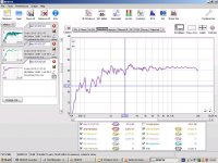
hmm ok i heated the membrane , to lower the resonance to see if it has anything to do with that. this is the result. max output before collapsing of membrane and creating an sort of machine gun sound. it 3 dB lower as it was. but the nulls are much less anoying and also it lowerd in fequency, still want to get rid of them
1. higher resonance, and higher voltage able
2. lower resonance and lower output possible
1. higher resonance, and higher voltage able
2. lower resonance and lower output possible
Attachments

Last edited:
"no more collapsing membranes"
Thats Cool!!
I was wondering at what bias voltage you were using.
It seems tp Corresponde to the experiences I have observed when running very high bias volatges. I never had any colapses using them but I did have a few when at lower levels and raising volatge it would recover.
This seems to go againist what others say about having have a high tension in order to maintain stability.
As you know I don't use high tensions and I never had a problem with diaphrgam stability when I use bias volatges above the point of 4.5Kv or so, Not even at 10KV.
At 10KV the force is so high in a .072" gap it has no choice but to stay in the center and even if you blow on the diaphragm it doesn't budge.
In cases were I had the frame loose enough to squeeze them to lower the tension (and resonance) I recall they didn't collapse at the higer voltage at all compared to the lower bias voltages.
I have also had however very strange effects at lower levels of bias before I would bring them all of the way up to a full charge, but once I did that I could lower the bias back down to the same level of the effects and the effects would be gone.
This may have been an issue due to the stator coating materials I use.
I Looked to see if it was a collapsing issue but I could not tell, but it could have been as it was very hard to see details past the mesh stator.
This is one of the main reasons my next build uses a more open design using TIG rod stators, That is to be able to have a better view of diaphragm movement
And yes every time you double the bias you will gain +6DB of efficiency.
At 8-10KV of bias I was getting +100-105db with just a small average signal and the amplifier really liked that!!
I don't recall what my final efficiency rating at a 1 watt level perbias voltage was, but I started at the same level as you at about 89-91db and once I had got to that point I was amazed as it matched that of the woofer.
This was a big struggle when I had got them out of the closet and got them running again back in 2010!
I had barely got any sound out of them at all and it took all of the power I had to do so, and the woofer just a few watts!!
We have come a long way my friend to prove that little panels can actaully sound great!
The dip in your graph could very well be cuased from nearby refelctions in your test area, I have experimented with several setups and one in particular set up (actually two) I was able to eleminate the reflections getting into my test mic and the FR came out flat as a ruler.
jer
its not reflection
tried to move it or damp it but its non of those its really inside the panel so i recon membrane.well with the lower resonance if i use the same bias it will flap like a machine gun, so have to lower it a bit until the fequency of flapping goes down and ends into silence. then upp it a tiny bit. i lost 3db due to menbrame stability. but! these are 3 stacks. when i remove one stator connection flapping stops. this could be the membrane near one of the Front(or rear) stators might be closer then to the rear(or front0 , or it is because its asymmetrical at the moment with membranes .
btw only eq used a low shelf of -4 db at 6khz
Last edited:
"this could be the membrane near one of the Front(or rear) stators might be closer then to the rear(or front0"
Yes, This most likely could be the issue, I had that problem on my large 7.5"x 21" panel where it didn't have ver y good support and was not perfactly flat, and on a few of my smaller panles wher the mesh had a few bumps in it as well.
This was hard to control unless the stator was perfectly flat.
Having a very small D/S also makes it harder to control as well as you said Asymmeterical.
Alot of the times I had found that that Flapping can be cuased from the HV fingers from the Bias connecting to the diaphragm through the air, this is what is cuasing the oscillations as it dischages a section of the diagphram.
I found that a good stator coating pretty much eleviates this problem but, would be very difficult with the material that you are using due to its fine mesh grade.
jer
I have never made one without a coating, but it is something that I should try in order to have a control unit to compare the other ones too.
Although my Frist Panels that were coated with a White paint they were nearly the same as having no coating.
I never reached the high performance with those that I did with my good super panel ( black one) even though I had used much higher voltages.
They never got to the level that thing did and I was stuck with using vlotages <3.5KV or else I would have arcing and stability issues with the very same D/S and surface area.
jer
Last edited:
Alot of the times I had found that that Flapping can be cuased from the HV fingers from the Bias connecting to the diaphragm through the air
Hmm what do you kmean by that? i thought the flapping is membrame collapses to on stator discharge then get drawn in again when it charged up again etc etc. the higher the voltage the higher pitch machine gun
making 2 more stators and membranes quick
to see if i can make it more symmetrical by adding at least one membrane. if that does not solve it i will add another one since it wont matter anyways and might be able to regain some of the loses from the lower bias.
Last edited:
I have never made one without a coating, but it is something that I should try in order to have a control unit to compare the other ones too.
Although my Frist Panels that were coated with a White paint they were nearly the same as having no coating.
I never reached the high performance with those that I did with my good super panel ( black one) even though I had used much higher voltages.
They never got to the level that thing did and I was stuck with using vlotages <3.5KV or else I would have arcing and stability issues with the very same D/S and surface area.
jer
but usually its the voltage of the trannie that arcs am i correct ? thats the reason why insulation is normally needed. safety and such
. i only see this pannel arc when i play it loud fullrange, or when i clip of one of the biases. it will arc to one of the stators instantly. if both are connected it wont. i think the bias of the next membrame sort of keeps the next one in line a bit or i might have not enough current to drive both multipliers and membranes, so when i disconnect on the other one gets the full current. and sparks. who knows i kind of liking the way it is now.... no heavy sparks btw if only high/mid frequency are used it works pretty fine without insulation. its the lower octaves that really makes these babys act like fireworks. most energy there
Last edited:
Oh i got one question, maybe you know they anwser since you are more into electronics.
when making a menbrame of the same surface area as the 2 stacked, is the capacity 2 that of one single one ? since the normal version would have 2 times the surface area of stator facing each other, because for 2 membranes i only use 3 stators isntead of the 4 that should be needed normaly when you have a normal panel of the same surface area
when making a menbrame of the same surface area as the 2 stacked, is the capacity 2 that of one single one ? since the normal version would have 2 times the surface area of stator facing each other, because for 2 membranes i only use 3 stators isntead of the 4 that should be needed normaly when you have a normal panel of the same surface area
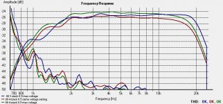
Sooo added one more stack.
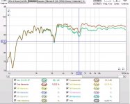
Well first measurement is from the original 3 stacked at max bias, without flapping. second is with added stack at same voltage (at least my power suplly is) 3rd is with max voltage before flapping.
an increase of ~2 dB, you can also see high fequency roll of starting to take effect. but since i eqed it i can bring it back also funny to see distortion go down a tiny bit. tomorow another day and i will try to add something to see if i can stop the flapping and see if there is anyhting left in it spl wise.
Well first measurement is from the original 3 stacked at max bias, without flapping. second is with added stack at same voltage (at least my power suplly is) 3rd is with max voltage before flapping.
an increase of ~2 dB, you can also see high fequency roll of starting to take effect. but since i eqed it i can bring it back
also funny to see distortion go down a tiny bit. tomorow another day and i will try to add something to see if i can stop the flapping and see if there is anyhting left in it spl wise.Attachments
One more thought on Post #109 what is the distance of your mic to the panel as this could Maybe cause some refelction from your very fine mesh (just a thought).
But in most cases I have found it to be some kind of reflection that cuases such steep dips in the response.
It took me many tries and adujstments to get that ruler flat line in my room.
I nearly covered everything in the room with blankets near the panel and mic. to finally get the results I was looking for.
I got similar dips on my last measurments with the thing steeing in front of my monitors as shown in the pictures I have posted.
Earlier tries back in 2010 when I had just one monitor I had found the cavity next to it that is supposed to hold a stack of CD's caused a dip around 200Hz to 300Hz or so and I stuffed that cavity and the dip went away.
Measuring the distance to the panel to the back of the cavity was in relation to a 1/4 wave of the frequency of the dips that showed up in the FR graphs.
The last graph you posted looks really nice!!!
THD measuremnts are tricky due to calibration of the levels but HOLMS seems to do a nice job of adjusting in approximating for this.
jer
Thoughts on post #113,
Typically, Yes the transformer voltages are much higher but you are still limited in peak SPL by only the resistance of the breakdown of the air.
Using a coating allows for a use of higher volatges all around thus increasing the efficiency.
Having built my Regulated Variable HV power supply has been a wonderful device and has allowed me to examine the actions of high voltage with a much closely controlled observations.
As you know that when the voltage is high enough the air breaks down and Corona Fingers start to form.
This is very hard to see at lower levels of just a few kilovolts.
But when you crank the voltage closer to 10Kv and above you can see thing more clearly as the fingers are much longer and more illuminant.
My supply is capable of close to 14Kv (13.5 or 13.8kv actually limited by its design and the opamps I am using as they are not rail to rail types) with an accuracy fo better than .01% I think at 1v per 1Kv of input control.
The fan is also connect to the varialbe side feeding the output stage so that when it ramps up I Know that current is being drawn from the output voltage as it is trying to compensate to maintain the set volatge, and it stays rock steady at the set voaltge and recovery is very fact when it comes to a full arc.
I have a scope shot of this to shoe the recovery time in the build thread of the supply when I made it.
So what I am getting at is that once I turned the voltage up I could see the corona quite nicely and very steady as it is a regulated supply and since it is just producing a voltage with no load the fan speed is very quiet.
As you start to introduce the ground probe to the HV output's corona they get a bit longer and you sometimes can get very close to them almost touching without them doing a Full Arc and Flashover.
Now as I mentioned at idle the fan speed is very low and as I move the ground probe closer I hear the fan start to ramp up faster.
Mind you that I have only brought the probe closer and have not caused a full arc yet, This tells me that there is a significant amount to current flowing from the output to the ground probe through the air in about 5/8" to 3/4" of an air gap.
Sometimes I can make it ramp up to full on from just a low voltage setting before it finally flashes over.
Meanwhile I am monitoring my output volatage and it is still holding steady at the voltage I had set it to.
Now this very same thing happens at just a Kilovolt or two as well only the corona finger aren't very visable or at all at that level.
So if the voltage in your gap gets just high enough the corona will reach at to the diaphragm and current starts to flow discharging a portion of the diaphragm.
Since this causes a imbalance of forces, it starts to oscillate just the same way a mechanical buzzer works, being the airgap is acting as your interupter combined with the movement of the diaphragm as well.
This is were it can stay stable as long as there aren't any lower frequency's causing the diaphragm to move at closer distance to the stator and cause the cycling to start as well.
An insulated stator can help this is the resistance of the staor coating will limit the current that is trying to discharge the diaphragm as well.
The thing I want to explore more about is usigng Higher voltage vs what we call normal ESL voltages of a few kilovolts.
As I was playing with my supply one day I found that as I increased to voltage the wavey shaped Clip Lead that I was using would suck right down to the glass plate that I was using to insulate my experiments form the surface of my desk.
I mean to push this wire down by my finger took a bit of force to do.
And it did it with a bit of lineararity as well.
Lets say the the wire had a 3/8" inch hump in it and at 14Kv the whole wire was sucked down to the glass.
And at 7Kv it only had about 3/16" hump, it did this with repeatability.
But what amazed me was that there was this much force to flatten the vinyl coated wire and there was no corona visable and no arcs of any kind, My desk was the ground plane and the wire was insulated from it only by a peice of glass.
When ran my panel at a full 12Kv it did so while the supply was full open and never got the that 14kv that it could produce, this was due too the limits of the integrity of the coating and the supply would start to ramp up quite quickely past about 11Kv so 12kv was the highest I got with it, but the efficiency was increadble!!!
Currnet was flowing and it was a matter of time before it would break down and burn again.
The hard push from using the bigger Crown DC300A is what did it.
But in reality it didn't need it I just wanted to find its bearking point since I was tired of repairing it and it was just getting worse beside.
It was to much for that particular build so it didn't last long as I had explained 100's of time probably already.
It was an interesting experiment.
My other identical panels that had white paint on them never reached the preformance I had gotten with those particular ones and they I would consider that they where still better than having no coating at all (but only slightly).
It may be possible to make just the mid/ttweets with no coating and get away with it, but I still say it is better to use it.
The coating integrity becomes a biggest issue as well at the higher frequency's, this is when I had most all of my failures and tried to fix them many times over.
jer
Last edited:
ger,
Higher bias reduces membrane collapse? I was running my CLS re-mylared and it was collapsing onto back stator at 3k. Any more voltage and more of the membrane would collapse.
I am buying different spars to raise the spacing a bit, to see if that helps - but curved panels are a nightmare to get correct. I would resort to wiping off the coating in the collapse area to keep section from collapsing. I figured that the surrounding boundary that had coating would "drive" the uncoated area still...worked ok, but not a good solution.
I also always wanted to reverse the polarity of the bias voltage to see if it would prevent collapse onto back stator... kinda think it would not matter
Last edited:
Thoughts on post #114,
This depends on how the stators are wired if they are just in series then the total capacitance is half that of a single panel.
Also the voltages applied to each diaphragm are 1/2 as well becuse they are in series.
If they are in parallel then you may have some gain with an increased excursion and this would equal out the loss of using 1/2 the surface area.
I forget which combination I used when I discoverd this.
It was also during this time I discoverd the reasoning that you should have the bias to each diaphragm isolated form each other with at least a 10Megom resistor feeding each individual diaphragm.
I only messed with this for a little while because at the time I was still sorting out my understanding of how the transformer works and drive issues.
Becasue of my cheapy Aiwa amplifier that I was using, it would shut down and I would have to unplug it and reset everything via remote in order to take another test!!
I did this probaly 100 times on some days for a few months straight.
I didn't have an SPL meter or a measurement mic yet at the time either.
I was just relying on what I heard and my voltage levels and gain settings on my mixer.
So, it burned me out so bad I dropped out for about a year and then decided that I had better finish my power supply First in order to get any farther.
jer
Ya, see that is a touchy situation John.
My last set of little panels where perfectly flat and uniform as was the stator coating on them as well.
Any number of reason's can cause and imbalance and make them collapse, I am thinking even a irregular diaphragm coating as well.
But definitely asymmeterical issues play a big part.
I am not saying that my panels never collapsed but they did some strange things when I would First power them up with a low bias.
But, once I ran them full open to 10Kv and then brought them down again to even as low as 1-2Kv I never got those weired issues I would get when I would first power them up.
I had described these effects in another thread before, but I never got the the point of nailing exactly what was causing it.
It could have been that my stator coating was too good, and was holding it's own charge until I had the bias high enough to overcome the residual charges and even out.
This concept had been disscussed once before.
jer
- Status
- This old topic is closed. If you want to reopen this topic, contact a moderator using the "Report Post" button.
- Home
- Loudspeakers
- Planars & Exotics
- sandwich esl ?Yummie