yes thd+N after ampboard-outputfilter into a load, load being part of noise and distortion creation, (out of audioband noise also being factor that could influence in audioband distortion measures, output class D ampboard usually get through additional LPF 7th order 20khz/22khz into measuring device for reliable distortion measures.(AES17)
im even wondering if a class D can make a square wave ? with the filter in the output ") my class D knowledge is verry limited to, connect and listen
my class D knowledge is verry limited to, connect and listen
i got more teeth like figures
if i am correct the sharp edges in a square wave consist of rather high frequencys, maybe the filter in Class D limit that as well ?
my class D knowledge is verry limited to, connect and listen i got more teeth like figures
if i am correct the sharp edges in a square wave consist of rather high frequencys, maybe the filter in Class D limit that as well ?
erm no , i used the esl that was connected, just wondering if it could replicated a square wave. but its not that big of a deal. not looking forward of finding out what is going on this time. since i dont want to go to deep into the class D (at this moment ) to much on my mind as it is
it looks like the newer version plays from 900hz and up compared to the small one that played from 1400hz crossover point. so i dropped it 500hz, but i encounter some more problems in the membrame stability area.
few reasons why its getting hard.
- 0.5mm spacing does not leave much room for error.
- Membrame area is bigger and collapses easy into a stator.
- stator area is bigger and is more prone to bending into one of the membrames.
i used 4 dots of silicone now, in the hope i could stabilize the membrame more and add some bias. for now it looks like i dont get more then 1-2 db more output. but i still hear when i put my ear close to it , some small sizling noises so either one membrame collapsed or i got some bad leakage(or bad connection) or corona. occuring.
(at this moment ) to much on my mind as it is it looks like the newer version plays from 900hz and up compared to the small one that played from 1400hz crossover point. so i dropped it 500hz, but i encounter some more problems in the membrame stability area.
few reasons why its getting hard.
- 0.5mm spacing does not leave much room for error.
- Membrame area is bigger and collapses easy into a stator.
- stator area is bigger and is more prone to bending into one of the membrames.
i used 4 dots of silicone now, in the hope i could stabilize the membrame more and add some bias. for now it looks like i dont get more then 1-2 db more output. but i still hear when i put my ear close to it , some small sizling noises so either one membrame collapsed or i got some bad leakage(or bad connection) or corona. occuring.
well cleaned everyhting, added dots to the opposite stators as wel, so i cant get it appart anymore without destroying everything. the dots are not only membrame control, but in this case also stator stability control i lowered the bias. i measured 380 volt on the input and its a 3 stage multiplier. so 380 *2 760 *2 1520 * 2 is 3040 volt, thats maybe i bit to much for such small spacing, i lowered it, and sizling almost gone now, hope it will be gone completely tomorow since the silicone is not dried completly.
i will take a look at the gain settings of the TPA3116 board, maybe i can tweak them up a bit, so i can lower bias a bit more to be safe and pump out some more into the trannie, since they can put out 50 watss into 4 ohm, it does not sound like hes having any trouble with ear piercing levels
usually this can be done with some resistors, but my board only has SMD components.. wich makes it a bit hard. also i cant find an exact layout of the same board where people have done this
i lowered the bias. i measured 380 volt on the input and its a 3 stage multiplier. so 380 *2 760 *2 1520 * 2 is 3040 volt, thats maybe i bit to much for such small spacing, i lowered it, and sizling almost gone now, hope it will be gone completely tomorow since the silicone is not dried completly.i will take a look at the gain settings of the TPA3116 board, maybe i can tweak them up a bit, so i can lower bias a bit more to be safe and pump out some more into the trannie, since they can put out 50 watss into 4 ohm, it does not sound like hes having any trouble with ear piercing levels
usually this can be done with some resistors, but my board only has SMD components.. wich makes it a bit hard. also i cant find an exact layout of the same board where people have done this
Last edited:
Hi,
the transformation factor shopuld be chosen as to achieve a good impedance matching. The low capacitance of a few hundred pF presents a very high impedance value that needs to be matched to the usual 4-8Ohms the amplifier is optimized for.
Say the panel measured 100pF.
After Zr= 1/(2pi+F+C) this means 160kOhms@10kHz, 320kOhms@5kHz and so on.
Lets assume 5kHz to be roughly the middle of the useable bandwidth, then the transformation factor would be:
U= sqr(320k/8) = 200!!
So, Wrinex thinking of 1:150 wasn´t too far off
jauu
Calvin
ps:
just before the output filter .... just beforewondering if a class D can make a square wave
Hi,
the transformation factor shopuld be chosen as to achieve a good impedance matching. The low capacitance of a few hundred pF presents a very high impedance value that needs to be matched to the usual 4-8Ohms the amplifier is optimized for.
Say the panel measured 100pF.
After Zr= 1/(2pi+F+C) this means 160kOhms@10kHz, 320kOhms@5kHz and so on.
Lets assume 5kHz to be roughly the middle of the useable bandwidth, then the transformation factor would be:
U= sqr(320k/8) = 200!!
So, Wrinex thinking of 1:150 wasn´t too far off
jauu
Calvin
ps:
just before the output filter .... just before
hahaha yeah calvin
he makes square waves at a rate of 200khz just before the filter about the transformer factor thingy, if i calculate it for a 4 ohm amplifier, thout would result in 1:280 ?
thats allot. Calvin
What if it is off ? what happens if i use a 1:120 instead of the calculated 1:280 ?? i mean i am using one right now, dont see anything weird. only thing is i know the amp likes to drive lower loads then 8 ohm. thats why i used 4 ohm as example.
So if i would make a trannie for this panel and this amp prefered it should have
verry limited primarie turns (since it does hardly do any low frequencys) and because this is the only way to get a high secondairy turn ratio without having to make to many sec turn and lose out on high frequencys? and prefferd ratio of 1: on a wopping 280 ?
Last edited:
If you are making an impedance matching argument, you would need to include the secondary winding capacitance which is often 500pF or higher(1000pF for Antek power toroids)....the transformation factor shopuld be chosen as to achieve a good impedance matching. The low capacitance of a few hundred pF presents a very high impedance value that needs to be matched to the usual 4-8Ohms the amplifier is optimized for. Say the panel measured 100pF....
I think Bazukaz argument for limiting step-up ratio based on maximum allowable stator voltages is a reasonable approach. With most 100W solid state amps capable of outputting 30Vrms(or more), a step-up ratio of 75:1 would keep that stator voltages for D/S=0.5mm just under arcing level while retaining full dynamic range capability. If a 200:1 was used, you would arc the panel with much over 12Vrms(20W).
Another benefit to this approach is that lower step-up ratios are easier to design and build without running into core saturation or HF limits at the top of the audio band. Now, if you are building an ESL that will only be driven with lower power tube or chip amps, the higher step up ratio makes sense. It is the only way to take advantage of the full dynamic range capability. Just don't forget about the voltage limit and accidently let a friend try out his high power amp on your ESLs(been there done that). In this case, a simple QUAD or Martin Logan style stator voltage limiter might be a good idea.
If you are making an impedance matching argument, you would need to include the secondary winding capacitance which is often 500pF or higher(1000pF for Antek power toroids).
I think Bazukaz argument for limiting step-up ratio based on maximum allowable stator voltages is a reasonable approach. With most 100W solid state amps capable of outputting 30Vrms(or more), a step-up ratio of 75:1 would keep that stator voltages for D/S=0.5mm just under arcing level while retaining full dynamic range capability. If a 200:1 was used, you would arc the panel with much over 12Vrms(20W).
Another benefit to this approach is that lower step-up ratios are easier to design and build without running into core saturation or HF limits at the top of the audio band. Now, if you are building an ESL that will only be driven with lower power tube or chip amps, the higher step up ratio makes sense. It is the only way to take advantage of the full dynamic range capability. Just don't forget about the voltage limit and accidently let a friend try out his high power amp on your ESLs(been there done that). In this case, a simple QUAD or Martin Logan style stator voltage limiter might be a good idea.
aah nice, might take a look(google search
) at the voltage limiter , since i intended to use this amp wich as you can see cant deliver that much power. i could use it in PBTL mode then i got 100 watts. hmmm but then i need 2 amps and 2 powersuplys on the other hand usually ears give out before you get to acring level, i mean i did not see or hear any arcing yet (on my class AB amp). and at this moment used it at levels way higher then any normal person would listen to, the bass department would already sounding like complete crap before i reach that level of spl that i reach with the panel alone in the high frequencies. hmm confused what to do
...oops, meant to add links to ML Limiter circuit and pic.
http://www.diyaudio.com/forums/planars-exotics/190698-martin-logan-sl3-crossover-2.html#post2613316
http://www.diyaudio.com/forums/planars-exotics/190698-martin-logan-sl3-crossover-3.html#post2686463
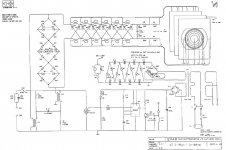
The later Quad limiters are attached on the secondary side of the step up transformer.
They are built from a string of zener diodes inside of a diode bridges.
http://www.diyaudio.com/forums/planars-exotics/190698-martin-logan-sl3-crossover-2.html#post2613316
http://www.diyaudio.com/forums/planars-exotics/190698-martin-logan-sl3-crossover-3.html#post2686463
The later Quad limiters are attached on the secondary side of the step up transformer.
They are built from a string of zener diodes inside of a diode bridges.
Attachments
Last edited:
AH thanks Bolsert, was looking on google and could not find anyhting and you scoop up a nice post about it
ai that still looks rather complicated, maybe for most this is simple as it gets but for me... what if i use the amp i use now, it has a maximum output voltage i presume. what if i adjusted the turns ratio for that to get a (nearly)max output before arcing? so people would hit the limits of the amp before anything tot he esl goes wrong >?
does mean if you turn it on verry LOUD the amp would be working in his max region, where class D tends to go beserk wth THD. so many options.
btw i always are flabbergasted about the Quad ESl63, how well designed it is. beautifull
and you scoop up a nice post about it ai that still looks rather complicated, maybe for most this is simple as it gets but for me... what if i use the amp i use now, it has a maximum output voltage i presume. what if i adjusted the turns ratio for that to get a (nearly)max output before arcing? so people would hit the limits of the amp before anything tot he esl goes wrong >?
does mean if you turn it on verry LOUD the amp would be working in his max region, where class D tends to go beserk wth THD. so many options.
btw i always are flabbergasted about the Quad ESl63, how well designed it is. beautifull
Last edited:
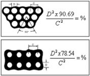
1.9mm center to center? just looking at the pic I guessed more like 1.6mm - 1.7mm....well about the holes i cant seem to find the file of the first 2 stators i made... but the 1 mm version has 1.9 mm from center to center.
In any case, this is < 30% open area, so not quite as open as your original panels.
Formulas for calculating open area percentage shown in pic #1.
If you don’t like to do the math, there are several online calculators you can use
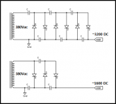
When you say 3 stage, do you mean 3 diodes and 3 capacitors? or 6 (ie often a stage is considered 2 diodes and 2 capacitors).…i lowered the bias. i measured 380 volt on the input and its a 3 stage multiplier. so 380 *2 760 *2 1520 * 2 is 3040 volt, thats maybe i bit to much
See pic #2 for estimated, no-load, voltage multiplier outputs for both.
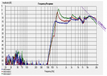
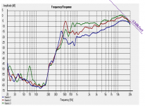
I noticed that all your measurements show a -12dB/oct roll-off at the top of the audio band. This 2nd order roll-off is usually associated with bandwidth limit of transformer or microphone(you had mentioned it was not calibrated). As an example, you can see the -12dB/oct roll-off in most of the Panasonic microphone capsules I posted. Most economy measurement microphones use the Panasonic capsules or something extremely similar.
http://www.diyaudio.com/forums/plan...request-amt-heil-diaphragm-4.html#post2586319
However, in attached pic#3 and #4, it appears that the roll-off point may be moving lower in frequency with increased panel capacitance from adding sections so that makes me think that it is related to the transformer. But, it could be a combination of both.
Although unlikely, it could also be your sound card, or soundcard driver.
If you haven’t yet, you might try performing the REW loop-back test to confirm that it isn’t sound card related.
I cheat...I keep a local key-word searchable index of posts I found useful....and you scoop up a nice post about it
Attachments
Last edited:
Ho Bolsert, i rechecked the spacing from the holes and it is indeed 1.9 center to center. i calcultates openeniss a few times but usually with a square pannel, that makes it easy to count te holes, since the programm i used does not let me see how many points i selected, i have to count them with square panel ofcourse only 2 rows.
About the Bias i used 2 caps and 2 diodes as one stage, as in you picture
same as here but used 3 instead of 5
yes the roll off. the thing here is i do have a calibrated Umik microphone, but ofcourse not my laptop. problem here is i can check that only with a loopback but then im not sure what i am checking my line/mic in or my output. because my calibrated mic is an usb device so it wont use the mic or line in.
but ofcourse when there is such rolloff then changes are verry high its the laptop at fault. (wich i dont think)
i could also measure it without dsp in between see what happens, ill do it now fast before i have to go
but usually with a square pannel, that makes it easy to count te holes, since the programm i used does not let me see how many points i selected, i have to count them with square panel ofcourse only 2 rows.About the Bias i used 2 caps and 2 diodes as one stage, as in you picture
same as here but used 3 instead of 5
An externally hosted image should be here but it was not working when we last tested it.
yes the roll off. the thing here is i do have a calibrated Umik microphone, but ofcourse not my laptop. problem here is i can check that only with a loopback but then im not sure what i am checking my line/mic in or my output.
because my calibrated mic is an usb device so it wont use the mic or line in.but ofcourse when there is such rolloff then changes are verry high its the laptop at fault. (wich i dont think)
i could also measure it without dsp in between see what happens, ill do it now fast before i have to go
Last edited:
Ok measured with and without DSP , well there is nothing wrong there, as one would expect. then i measured the panel with primaries in parallel and once with prim in series. does this tell anything? ofc i got lower output, but it looks like the 12db point shifted to, or is it just flatened?
the loopback i can maybe measure tomorow, since im not sure if i got such cable around might need to make one.
BTW can it also be seen in an impedance response measurement? i could make one more easy then getting 2 mini jacks at the store
the loopback i can maybe measure tomorow, since im not sure if i got such cable around might need to make one.
BTW can it also be seen in an impedance response measurement? i could make one more easy then getting 2 mini jacks at the store
Attachments
Last edited:
1.9mm center to center? just looking at the pic I guessed more like 1.6mm - 1.7mm.
In any case, this is < 30% open area, so not quite as open as your original panels.
Formulas for calculating open area percentage shown in pic #1.
If you don’t like to do the math, there are several online calculators you can use
Oh god i feel like a tard
i always calculated the area of one hole , times the holes then the total amount of surface area they are sitting on and calculated it back to percent hahaha i found the calculators THis is exactly what i need !!!! i even read ur post and still did not get it.... dumbthis makes everything so much easier
Last edited:
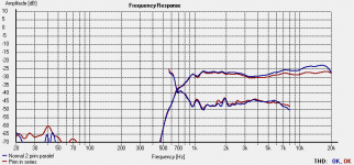
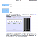
Yes, an impedance .vs. frequency measurement made with REW would tell whether it is the transformer causing the HF roll off. If it is, you will see a minimum right before the roll off starts, and phase will pass thru zero. But, you would still probably need to perform the loopback calibration shown in the manual to ensure validity of impedance measurement.BTW can it also be seen in an impedance response measurement? i could make one more easy then getting 2 mini jacks at the store
Did you shift the series measurement up in level by 6dB to match the parallel measurement so the HF difference was easier to see?.. i measured the panel with primaries in parallel and once with prim in series. does this tell anything? ofc i got lower output, but it looks like the 12db point shifted to, or is it just flatened?
I agree, it does look like the roll off point shifted.
Attachments
Last edited:
Well i indeed upped the volume to match the other Measurement. I indeed use rew wich I calibrate with the test resistor, but I dont have a voltage devider yet to use a power amP, so I am limited to the soundcard output.
I measure it with the panel connected I assume? Can do both ofc then we might see what happens. Also I will grab my solo sound trannie and see what is does compared to this one.
If that one works , then it must be the trannie. Still will measure them.
I measure it with the panel connected I assume? Can do both ofc then we might see what happens. Also I will grab my solo sound trannie and see what is does compared to this one.
If that one works , then it must be the trannie. Still will measure them.
For HF impedance trends, the soundcard output should work just fine.… I dont have a voltage devider yet to use a power amP, so I am limited to the soundcard output.
Yeah I agree, measure both with and without panel connected to see the effect.I measure it with the panel connected I assume? Can do both ofc then we might see what happens.
You might also measure with primaries in parallel, and in series.
- Status
- This old topic is closed. If you want to reopen this topic, contact a moderator using the "Report Post" button.
- Home
- Loudspeakers
- Planars & Exotics
- sandwich esl ?Yummie