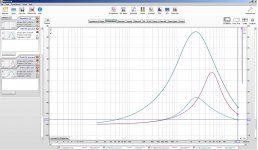
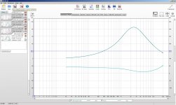
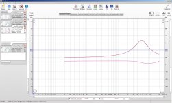
The plot vertical scale should be in (ohms), not (dB).Here are the impedance measurements.
Did you select [Impedance] in measurement window?
Take a measurement of a 2ohm - 10ohm resistor to makes sure the measurement setup is working correctly.
It should show the correct resistance magnitude with phase close to zero for most of the audio range.
Attachments
Last edited:
Ha! I have never seen dB and ohms plotted together.i can make some screens where it is on the left if you like")

Can you show the phase for the impedance curves?
I think you may need to go to the individual impedance measurement tabs to see it.
there we go , just noticed the alt button to make a screenshot only of the window needed instead of a dual screen haha
wel here they are, dont forget i scaled them to get the most accuracy as posible so a higher peak doesn not mean a higer value, since the values on the side change as well
1. With esl primary paralel
2. With esl prim in series.
3. Without ESL prim paralel
hahawel here they are, dont forget i scaled them to get the most accuracy as posible so a higher peak doesn not mean a higer value, since the values on the side change as well
1. With esl primary paralel
2. With esl prim in series.
3. Without ESL prim paralel
Attachments
Last edited:
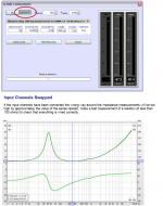
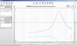
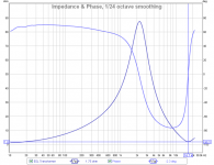
I'm still not sure what to make of the measurements. The general shape of the impedance magnitude looks about right, but the phase is all wrong. It should be (+) below the peak (ie inductive), pass thru zero at the peak and then (-) above the peak(ie capacitive), and finally passing back thru zero at the dip which defines the HF roll off point.See pic #1 for example toroid transformer driving large ESL hybrid panel....here they are, dont forget i scaled them to get the most accuracy as possible...
You might try measuring an 8 ohm resistor and make sure the phase is zero over most of the audio band as shown in pic #2.
If your impedance magnitude is correct as shown in your plots, then the transformers are not the cause of the -12dB/oct roll off in your response.
Perhaps you didn't have the mic calibration file loaded properly when you took the measurements with HolmImpulse?
Attachments
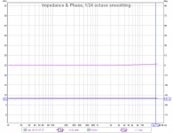
i will measure a resistor to see what happens to the phase, btw in the calbration one the rsistor stays at 0 degree. but i will measure another resistor as well (dont have an 8 ohm gone be something else in the region of 1-4)
i begin to wonder as well what it might be, i did had the correct file loaded.
gone be something else in the region of 1-4)i begin to wonder as well what it might be, i did had the correct file loaded.
Last edited:
Hi There!!
Somewhere I had read that it is best to use the added resistance that you normally would for actual use as your reference.
Typically this would be about .47 to 2 ohms as this would give a far better idea of your impedance curve for your real world application.
I have tried several different values when doing impedance curves and some programs change the peak in the curve drastically and some not so much, namely early versions of SimpleS.
REW seems to do a very good job of repeating the curve with various values of resistance's although you may still find some slight variances.
I never sat down and did the long hand math method to find out what the error is (if there is any) , I have asked why this is and nobody has given any insight to this yet.
Since I have been playing with PIC chips lately I have though about creating one just to do impedance measurements, AD, LT and TI have a few very nice chips already designed to do these functions.
I am enjoying this thread very much you seem to be finding most of the things I have found with small ESL's as well.
It wasn't until I could get the Bias up into the 5Kv-8Kv range and the transformer ratio to 150:1 and higher that mine would finally match the efficiency of my woofers in the 89db to 91db range.
And the D/S at 1.65mm to 3mm for the lowest frequency's down to about 150Hz to 180Hz.
Below this diaphragm resonance was an issue at 70Hz to 110Hz or so.
Typically about 220hz was as low as I could tell where the full range of vocal's was not effected if one was adamant about actually getting that low for such reason's.
It took a lot of diaphragm movement with a D/S in the 2-3mm range to not clip at those frequency's.
Not to mention increasing the bias and doubling up on the number of cores used to keep them from saturating at such levels while having a high enough impedance for the amp to stay happy.
The impedance at the lower frequency's are solely based upon the primary winding's inductance and the panel as no effect with its very small value of capacitance, as this is shown by the impedance curves you have already shown.
If two primary winding's of the same amount of turns have mutual inductance (on the same core) their values do not change if the are tied in parallel.
And when they are tied in series that have 4X the inductance that a single winding of the same amount of turns does.
This means 4X the impedance as well for the lower frequency's.
The draw back is halving of the turns ratio.
The same goes true for the secondary side, but the main draw back of tying secondary winding's in series is the doubling or more of the secondary winding's extra capacitance.
If the cores are separate and don't share any mutual inductance then tying two winding's in parallel or series follow the very same rules and calculations as of those for resistors in Parallel for half the value or series for double the value.
I think the best thing is that when the secondary's of two separate cores are tied in series their self capacitance is in series as well.
I have found this to be of benefit in one way although it takes four cores to do so.
It allows me to get my double the ratio that I needed (160:1 vs 80:1) and not have any more capacitance than that of using two cores while keeping my overall impedance aprox. 1.41 to 2 times higher (for the amp) than that of the 2 core method.
Meanwhile this also extends my core saturation point an octave lower too!
The primary inductance values set the bar for the whole transformer and this is the main reason why I say start with the biggest core that you can afford especially if you are trying to get fairly low.
The core I had chose to make a transformer may seem to be over kill especially for just a small ESL but the larger the core the least number of winding's it will take to reach my goal and will be only one core instead of 4 or 8 of them.
I have found that my Desktop ESL design sounds better when it is crossed over higher at its natural crossover point due to physics and its size anyhow.
So making a single transformer for the 500hz to 1000hz cutoff point makes it that much easier as well.
I have been working on recipes for the larger panel systems for DIYer's as well but I just haven't gotten the materials to do so yet.
I have calculate such transformers with large cores and only 2000 to 3000 turns for the secondary for use down to the 120hz to 180hz range, maybe lower.
This is also allowing me to use a rather thick inter winding insulation layer to keep the residual capacitance at an extreme low, we shall see.
And a pair or maybe a quad set could be made for around $35 to $60 a piece.
This 2X to 4X the performance for the same to almost half the cost of the current methods.
But since this is DIY you would have to wind them yourself !!!! He,he,he,he
Once I do get a good working model going I will look into how much more it would cost to have a batch special wound, but don't bet on it being cost effective at that point due to the special instructions for construction.
Cheers!!
jer
Sorry did not get to the resistor testing, had/have some major isues with my CNC. its not moving at the speed i want i told ya i changed a motor since it was acting weird. but the problem persists. despite the new motor . i wont go in details in what i do think is the cullpit but thats where my time goes, i need it to be fixed since i also produce some small funrniture with it.
Thx gerald for ur reply, ! nothing in the mail yet ? hope it arrives soon. i tried one of my test panels yesterday. compared to my stacked it has around 6-8 db lower output. but still sounding pretty nice, and extends much lower (i sued foam for spacers and they creep next time i go for slid spacers) res was lanind ojn 150 hertz thats almost 2 as low as it was when i made it . aah well it let me corss lower with a 48db oct filter i could easy cross at 450. sounds nice as well. im kind of in dubio what to do for the final speaker. this stacked version is nice small has better dispersion and higher output. downfall incredible higher crossoverpoint, and is verry hard on tolerances. 0.5 mm material is verry thin and bends easy. in the straight panels i send you that should not be a problem but more a benefit that they are so thin. you can glue them to any support structure. and dont have problems with deep holes. resonances etc.
since i got som many panels left i might make a long version stack 3 or 4 above each other. and make the membrame wider then the pcb panel to lower resonance. acoording to fikker (some dutch esl guy) peaks at 100 hetz would be possible with a dc spacing of 1 mm. i would cross at 300 -350 then with 48 db oct there are not that much peaks left in the 100 hz region to hit the stator.
Looks like you know allot about transformer design?, still wanting to make cheap affordable trannies for the 300hz and up region.
how special is ur contrstruction ? something with bank winding and such ?
i told ya i changed a motor since it was acting weird. but the problem persists. despite the new motor . i wont go in details in what i do think is the cullpit but thats where my time goes, i need it to be fixed since i also produce some small funrniture with it. Thx gerald for ur reply, ! nothing in the mail yet ? hope it arrives soon. i tried one of my test panels yesterday. compared to my stacked it has around 6-8 db lower output. but still sounding pretty nice, and extends much lower (i sued foam for spacers and they creep next time i go for slid spacers) res was lanind ojn 150 hertz
thats almost 2 as low as it was when i made it . aah well it let me corss lower with a 48db oct filter i could easy cross at 450. sounds nice as well. im kind of in dubio what to do for the final speaker. this stacked version is nice small has better dispersion and higher output. downfall incredible higher crossoverpoint, and is verry hard on tolerances. 0.5 mm material is verry thin and bends easy. in the straight panels i send you that should not be a problem but more a benefit that they are so thin. you can glue them to any support structure. and dont have problems with deep holes. resonances etc. since i got som many panels left i might make a long version stack 3 or 4 above each other. and make the membrame wider then the pcb panel to lower resonance. acoording to fikker (some dutch esl guy) peaks at 100 hetz would be possible with a dc spacing of 1 mm. i would cross at 300 -350 then with 48 db oct there are not that much peaks left in the 100 hz region to hit the stator.
Looks like you know allot about transformer design?, still wanting to make cheap affordable trannies for the 300hz and up region.
how special is ur contrstruction ? something with bank winding and such ?
Last edited:
Nope nothing yet , still waiting.
It took me the better part of 2010 to 2012 to finally get a hand on exactly how those mysterious thing work, but it is amazingly simple now that I know!!!
The special requirements are that their would be absolutely no winding overlap and each separate secondary winding not over lapping the other one.
Have each one in its own half of the core or split them up into quadrants, as I am not sure exactly how much leakage inductance this would introduce I have several patterns to think about.
This wouldn't be a problem for small low capacitance panels but it may for a larger one that is not electrically segmented.
I had been planning insulation layers as thick as .050" or even as high as .1" if i can get away with it between to core and adjacent winding layers.
Thus another reason for using such a large core of a toroid type.
As each layer goes on this will make the inside diameter smaller and will limit how many turns the next layer can hold without any overlapping turns.
Then there is the wire gauge I am guessing that 30 ga. is sufficient but if I can use 28 ga. or even 26 ga. this would warrant a wider margin for any turns failing should the panel breakdown and arc as the thing will be capable of at least 30Kv of output.
Unlike the Antec that I was testing and failed at 4500V !!! :/
Luckily I was able to fix that one.
But, The cores that I have been using (210 watt types) have a larger gauge wire and I have yet for one to go bad even after my panel broke down with the Crown DC300a running at full power and I let it burn to a short as the screen turned bright orange and still no failed winding's!!
I have four of the cores stacked up and arced between them with a big pow and still no failed core has happened.
I want mine to have that kind of durability and they will with all of the extra measures that I have planned for it.
After all of that I am hoping that my transformer capacitance will be below 200pf and no more than about 300pf.
The cores are very reasonable in the $30 to $50 range for about 1867 to 3548 watt or more from Alpha Core (PN# 120-150),
Silicon Steel Toroidal Cores - In Stock
A smaller cores for our little panels or only about $5 to $10.
The PN# 60 is rated at 396VA and is only $11.51 and I am using 2 to 4 210VA cores at the moment!!
For instance that core would only require about 450 turns or so for 36V in and 1:200 ratio with a cut off of 360hz or so just as an example.
This would be very easy for a DIYer to build up in one night or two.
PRI-22 turns and each secondary 2 x 220 turns, or 110 turns each for 1:100
This is calculated from the core specs of .274 Volts per turn at 60Hz
Making one specific for the higher range is easy!!
It is when one wants to get lower such as 120 hz and lower things get big and expensive.
For the design I just presented, in order to get to 120hz, it would require 3X the amount of winding's.
Or, just limit it to no more than 12v of input signal rather than the 36V that I had figured it up for a large power amplifier.
jer
P.S. After I had just posted this post, I went out to check my Mail Box and the panels have Arrived!!......Safely!!!!
WoW....That was Fast!!!!.
They are the exact same size of the ones I burned up I can't wait to get started on a frame and have them running, Thank you so very much!!!
I will have some pictures for you later.
Cheers!!!!
Last edited:
Looks like you know allot about transformer design?, still wanting to make cheap affordable trannies for the 300hz and up region.
Hi,
Perhaps you have missed numerous threads about mains toroids. Your frequency range perfectly fits their capabilities. I was even able to use a large stack of those to go full range. Make a deep search in old threads
.Regards,
Lukas.
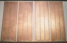
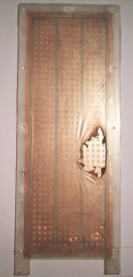
Here is a picture of the PCB Stators that was sent to me for testing.
They look very nice and the repeat ability is pretty good too as long as the boards are stacked going the same way.
I am sure that you are aware of this as you said you are still working on it.
Otherwise they look nice and thank you for sending them to me.
The size is exactly the same size as the panels I had burned up except it is 1/2" longer, it is all good!!
It will even fit my new TIG rod frames as well, just need to make some support pieces and it is a bolt on unit!! He,he,he
The active area as measured is 810mm X 2600mm with 516 3.5mm holes in three sections of 12x43 holes.
I calculated this to be a 23.5% open area as 4963.92mm^2 / 21060mm^2.
Due to the size of the holes this shouldn't be to much of an issue, we shall see once I get them running.
I think that one of my painted mesh stator version's had a fairly low open area in this range as well.
Cheers!!!
jer
Attachments
Nope nothing yet , still waiting.
It took me the better part of 2010 to 2012 to finally get a hand on exactly how those mysterious thing work, but it is amazingly simple now that I know!!!
The special requirements are that their would be absolutely no winding overlap and each separate secondary winding not over lapping the other one.
Have each one in its own half of the core or split them up into quadrants, as I am not sure exactly how much leakage inductance this would introduce I have several patterns to think about.
This wouldn't be a problem for small low capacitance panels but it may for a larger one that is not electrically segmented.
I had been planning insulation layers as thick as .050" or even as high as .1" if i can get away with it between to core and adjacent winding layers.
Thus another reason for using such a large core of a toroid type.
As each layer goes on this will make the inside diameter smaller and will limit how many turns the next layer can hold without any overlapping turns.
Then there is the wire gauge I am guessing that 30 ga. is sufficient but if I can use 28 ga. or even 26 ga. this would warrant a wider margin for any turns failing should the panel breakdown and arc as the thing will be capable of at least 30Kv of output.
Unlike the Antec that I was testing and failed at 4500V !!! :/
Luckily I was able to fix that one.
But, The cores that I have been using (210 watt types) have a larger gauge wire and I have yet for one to go bad even after my panel broke down with the Crown DC300a running at full power and I let it burn to a short as the screen turned bright orange and still no failed winding's!!
I have four of the cores stacked up and arced between them with a big pow and still no failed core has happened.
I want mine to have that kind of durability and they will with all of the extra measures that I have planned for it.
After all of that I am hoping that my transformer capacitance will be below 200pf and no more than about 300pf.
The cores are very reasonable in the $30 to $50 range for about 1867 to 3548 watt or more from Alpha Core (PN# 120-150),
Silicon Steel Toroidal Cores - In Stock
A smaller cores for our little panels or only about $5 to $10.
The PN# 60 is rated at 396VA and is only $11.51 and I am using 2 to 4 210VA cores at the moment!!
For instance that core would only require about 450 turns or so for 36V in and 1:200 ratio with a cut off of 360hz or so just as an example.
This would be very easy for a DIYer to build up in one night or two.
PRI-22 turns and each secondary 2 x 220 turns, or 110 turns each for 1:100
This is calculated from the core specs of .274 Volts per turn at 60Hz
Making one specific for the higher range is easy!!
It is when one wants to get lower such as 120 hz and lower things get big and expensive.
For the design I just presented, in order to get to 120hz, it would require 3X the amount of winding's.
Or, just limit it to no more than 12v of input signal rather than the 36V that I had figured it up for a large power amplifier.
jer
P.S. After I had just posted this post, I went out to check my Mail Box and the panels have Arrived!!......Safely!!!!
WoW....That was Fast!!!!.
They are the exact same size of the ones I burned up I can't wait to get started on a frame and have them running, Thank you so very much!!!
I will have some pictures for you later.
Cheers!!!!
I was off on my calculations I forgot another zero.
So that is 22 primary and 2200 for the secondary for 1:100 ratio.
This comes out to approximately 4 or five layers for non overlapped turns
I had calculated approximately 650 turns on one layer for the inside diameter of 2.125" of the #60 core using .011 dia. wire (30 ga.) not including any insulation layers.
Still not to bad, But sorry for the mistake and any confusion if I have caused any.
An even larger core will reduce the turns count even more.
I kept looking at the figures and I knew that something wasn't just quite right!!

jer
Last edited:
Geraldi am glad you received them in good order! did you burned one membrame already ? you must flip the copper to the outside , ooooh i now see you only have it there as comparison haha thought well thats fast , burned already . the open area i used was based on a panel from the brand solosound, although they used even larger holes. always likes the efficiency from that panel and never noticed anything weird from the low open area, so i adopted the same open area.
they used 0.8mm - 1mm pcb, dc spacing of 1mm and a whopping 5.5Kv bias,
also yes they are not exact mirror image i noticed, its not the cnc that failed rather the CAD program or CAD user when you put them on top of each other they are indeed exactly the same just not when you flip one
Thx Bazuka , no i did not miss the Antec threads thing is i bought some similair trannies from amplimo well know transformer company in the netherlands, 2 x teroids 6 volt-220 but they suck so hard, there are almost no high frequency and the stepup ratio even in paralel is just to low. . or the cheaper ones sound better, and i have to try those as well.... aaah all the money
, ooooh i now see you only have it there as comparison haha thought well thats fast , burned already . the open area i used was based on a panel from the brand solosound, although they used even larger holes. always likes the efficiency from that panel and never noticed anything weird from the low open area, so i adopted the same open area.they used 0.8mm - 1mm pcb, dc spacing of 1mm and a whopping 5.5Kv bias
, also yes they are not exact mirror image i noticed, its not the cnc that failed rather the CAD program or CAD user
when you put them on top of each other they are indeed exactly the same just not when you flip one Hi,
Perhaps you have missed numerous threads about mains toroids. Your frequency range perfectly fits their capabilities. I was even able to use a large stack of those to go full range. Make a deep search in old threads
Regards,
Lukas.
Thx Bazuka , no i did not miss the Antec threads
thing is i bought some similair trannies from amplimo well know transformer company in the netherlands, 2 x teroids 6 volt-220 but they suck so hard, there are almost no high frequency and the stepup ratio even in paralel is just to low. . or the cheaper ones sound better, and i have to try those as well.... aaah all the money
Last edited:
Yes, I figured it was an error in your program setting as one set of holes is about 1mm off center with the other two sets, No biggy!! He,he,he,he
That burnt diaphragm was from the panel I had burned up and was just sizing it up.
I will show you the progress as a go, I am going to build special a set of frames just for them and see if I can push that bias all of the way up like the last ones.
But without burning them !!!
I used to run them close to 8Kv all day long.
jer
Yes, I figured it was an error in your program setting as one set of holes is about 1mm off center with the other two sets, No biggy!! He,he,he,he
That burnt diaphragm was from the panel I had burned up and was just sizing it up.
I will show you the progress as a go, I am going to build special a set of frames just for them and see if I can push that bias all of the way up like the last ones.
But without burning them !!!
I used to run them close to 8Kv all day long.
jer
8 kv bias? well if you used 2 or 3 mm spacing like you last one that should be possible. i ran one with 1mm spacing at 5
looking forward also looking forwar to move forward
kind of having some problems here one after another with my machine hmm ok, i still was wondering why my 6 volt teroids did not deliver while everyone was so happy with them. , i changed them from the class D to the AB, oh boy, instead of a 12db slope down at 8Khz i get a major peak at 13khz that drops to normal level around 18Khz. any clue on why its not woring on my class D ? the other transformer did not seem to care much about the amplifier.
as of now they are prety usefull, if i had a bigger panels (for more output) or use 4 of them. hmm but still have to find out why the class d is having a 12db oct filter from 7 khz with this tranformer. might need to do an impdance measurement tomorow, maybe someone can shine some light on why they act weird on class D.
but still have to find out why the class d is having a 12db oct filter from 7 khz with this tranformer. might need to do an impdance measurement tomorow, maybe someone can shine some light on why they act weird on class D.- Status
- This old topic is closed. If you want to reopen this topic, contact a moderator using the "Report Post" button.
- Home
- Loudspeakers
- Planars & Exotics
- sandwich esl ?Yummie