I meant in the PSU section only.
That was clear, but my b1 is also built with GR's, I plan to rebuild it with BL grade as soon as I have them.
Tonight I had a good listening session, and it seems adding the 330uF caps did something to the staging of the sound. My Mission 702e speakers always sounded good, but the sound never was bigger than the speaker, tonight it was for the first time. An unexpected result, I did not know these speakers could do that. Had this before with newer Missions that have a tweeter with better dispersion, they have shown it on the same source and power amp. It seems I have always overlooked the importance of a good preamp...
So the next step will be adding more 10R resistors in parallel with the CCS, and see how far I can go before reaching a temperature limit on the transformer or the heatsink. I have put the heatsink on two small blocks so it is lifted 1 cm. Result: 8 degrees down in temperature. That headroom needs to be filled.
Is there an argument against installing a switch, to have it running with just the 2x47R for background listening ( wallpaper sound ) and adding the extra parallel resistors in the other position for real listening? Advantage would be to limit the power consumption when it does not really matter.
Use the BL only in the audio section so to save some and to not disrupt your now reached good current matching you built with GR in the PSUs mix.
Have you listened to your Mission speakers with those green 0.22u Russian caps alone as well?
Apply the two tier current mode switched thing only if you will find no oscillations or augmented noise by scoping the rails for cabling and switch. A capable relay maybe a better local solution if you will see degradations with the other stuff.
I think I should improve chassis ventilation,few holes in the bottom and top of case will do the job...Temperature in the long term on weak Led maybe. Is it a high temp hot-rod?
Thank you Salas
Ok, will leave the PSU alone.
Yes, all real listening tests have been done in the same installation:
Modified squeezebox Duet, with linear power supply
L15d power amp
Mission 702E floorstanding speakers
The only thing that might be in play also is that the last time I had a good listening session the B1 was powered on for a couple of hours, not moved from my bench, plugged in and playing directly. Also break-in can play a role here. So to be sure I have to desolder the caps again to judge their effect.
A relay would be easier to route the internal wiring, so that might be the best idea!
Thanks Salas for the really valuable support here!
No, did not have one in this value, so used the russian PIO, K42Y which is still in place, just soldered the 330uF in parallel to it.
I would not know where to start to calculate a best value for this cap. Earlier posts mention excellent results with a russian teflon cap of 0.22uF
Would be interesting to know what the best value and sort of cap would give the best results here. I have some larger caps that I could try, but it is not that easy to judge the results, as all caps need some time to break in, and audio memory is known to be tricky when not blind a/b testing...
It would be best to measure the result, and with the 330uF in place the already minimal noise at the output of the psu in about half of the value with only the .22uF in place. This is down to a level that my oscilloscope can hardly display at 2mV/div
All those things have been pursued in the past by some members but since the threads are old and long I will try give you the gist of the argument.Did you also tried a film cap instead of the 330µF? If so...I know what to do when building mine!
Among you is the best choice 330µF?
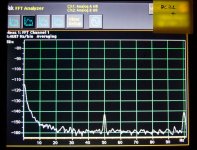
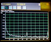
The higher the uF value filtering the voltage reference the less 1/F noise mainly. 1/F or flicker noise is the rising build up to the far left spectrum of a chart we encounter in all things electronic and some other in physics.
I had presented incremental simulations for the reg part in the past. Beyond 100uF gains slow much for the full band's filtering benefit and only 1/F gets better. About 1000uF is a practical level off. Mind you the charge can kickback to the associated Jfet in case of a mishap. Not common, maybe if probing the wrong way or during a wider failure.
Since different applications circuits have different soft spots regarding integrated noise level and its spectral characteristics, like some MC phono vs a buffer pre vs a digital clock etc. there was some flexibility built in the Hypnotize pcb so to have positions both for electrolytic and film Vref filtering capacitors. The Wima MKP10 0.22uF was chosen subjectively by some members vs other logical cost and available MKP parts they compared. PIO caps are inferior to MKP for HF filtering.
Same members concluded they prefer the film cap for tone especially in the rendering of female voices in the DCB1 context. Maybe the parasitic characteristics of the electrolytics vs the films given the sufficiently low noise of this reg when feeding a no gain line level circuit. When non filtered than only lightly in the HF for minimum wide band noise control from the film cap.
I have 100uF standard in the Mezmerize as originally voiced, the Hypnotize has space for options.
As you understand its a decide for yourself thing in the context of your taste and audio system in the Hypnotize.
Here are +/- PSU noise charts done by a member from Spain on a Mez once and shown sometimes before. Has the 100uF Mez standard filtering. 1/F climb can be seen to the left. Also the 50Hz and 100Hz European mains hum and its first harmonic pick up on the rails in the context of a fully built and wired standard Mezmerize with an unshielded 50VA toroid in the same small box.
Attachments
I have problems with my new class d subwoofer amplifier. The old sub amplifier was a class a/b I used the high level input and it played nice.... The sub is a System Audio Subelectro 175.
After I got the class d sub amplifier, I have tried both the high level input and xlr to unbalanced input (rca) but without any success, there are almost no sound in the sub.
My DCB1 are build fully balanced. To connect the sub from the dcb1 I used Hot and shield from both channels.
My sub have been tested by the manufacturer and they told me that it's working fine.
Why won't my subwoofer play with my dcb1?
Maybe a little offset triggers some protection circuit in it? Try with a coupling cap to confirm.
Still quite a newbie. So do I place the coupling cap on hot from both channels? And what value should it be?
In series with each hot and it can be 10uF if the sub is 10K input impedance or 4.7u if its 20K impedance and so on and so forth. Maybe just 100 Ohm buffer resistors in line with the sub output could be an answer if its some weird isolation issue from the main output for that sub. Or curiously grounded and needs a chassis ref on the cold, who knows. Start with the caps. Scenarios elimination method.
- Home
- Source & Line
- Analog Line Level
- Salas hotrodded blue DCB1 build