Normally yes when they got op-amp output but there are also some "esoteric" models with tube and no cathode follower stage or a transformer. In case of doubt when there are unexpected sonic clues you can always check their source resistance. Or get a 50K Tocos too since cheap from that Taiwanese seller and compare the 10K. If the differences won't count in your book you may use the 50K and never think about unexpected sources drive might again.
That measures the effective source resistance.Use a steady signal. Measure your source's output. Then load it with a trimmer, say 1K. Turn the load down until the output is half than unloaded. Remove and measure the trimmer, that represents the source resistance.
It does not measure the current capability of the output stage.
You might counter by saying that any source that can drive a 1k0 load must be good enough.
Not necessarily, it could be collapse of current supply that is giving the apparent ½emf on the temporary load.
The test as proposed cannot tell the difference between voltage reduction due to equal resistance/impedance in the send and receive circuits or overload on current demand reducing the output voltage.
A 10k load and a 1nF of capacitance needs more current capability than a 1k load.
Last edited:
Driving X interconnects is making it complex for a simple rule of thumb. I would say stick to 1/20 resistance ratio for typical 1m home system wires. The DCB1 current capability is IDSS btw for those who want to exactly analyze when they know the rest of the system drive parameters towards the main amp which is maybe located further away some times.
I too like the 20:1 ratio.
For a 220ohms B1 that gives a recommended load impedance of 4400ohms, use >=5k for a set of loads.
For a 100ohms DCB1, that gives a load impedance of 2000ohms.
I consider that too low. again >=5k is appropriate.
Both of the above rely on moderate capacitance loading.
Long cables are not suitable.
0.5m to 3m cables with moderate RF filtering in the Receiver are very suitable.
Salas and AndrewT, thank you both for the insight.
I measured the output of the Squeezebox, it is about 8,5 Ohm ( yes, that low )
Checking a couple of service manuals that I saved gives the following:
Philips: range from 120Ohm to 1K
Pioneer does not specify anything
Technics SL-PG490 says 1K, load impedance greater than 10K ( here's 1:10 )
Sony only specifies output voltage at 50K, and says load impedance greater than 10K.
When I demo the repaired players they can be connected with a 50 cm interlink of standard plus quality ( simple interlink but not the very cheapest type that fall apart by looking at them ). I cannot demo with expensive interlinks because they grab the connector with too much power to easily put them on and off the gear to be demonstrated.
Will 10K be fine ( enough for demo purpose? )
For personal use it is only the squeezebox, and that will be 1:100 so more then fine
New test board
Hi Salas,
I decided to get new boards from TeaBag as I messed up too much with the first one and damaged it in the process (overheated eyelets, some needed jumpers...;-( ....)
All this because of my stubbornness to get perfectly matched measurements... Well, you know the story .
Anyway, I finished building to new board and measurements are as follow:
LED (quintet):
9,92v left and 9,90v right
VDrop:
1,38mA left and 1,19 right
LED (triplet across the 100R):
1,03V left and 0,98V right
DC Offset:
0,2mV left and 3,1 mV right !!!!!
Now, as you already guessed, I am concerned about the DC offset on the right channel.
I have to admit I didn't match the MOSFETS. I guess they could be the culprit.
Question is, is it still OK to go like this or it is mandatory to try to "close the gap" between DC Offsets?
I am sick and tire of waiting and want to get the thing playing music. Damn !!!
Everything is ready. Just need to pop the board in...
Still, if you recommend to make changes prior to going forward, I'll pay great attention.
I wouldn't want to have an imbalance in sound because of this.
I invested a lot of money (by interest and also for fun) in this project and I have bought A LOT of resistors in order to test them. Can't wait (OK just a little more...maybe).
I want to get the thread "DCB1 resistor tryouts" going. Can't wait for the tests to begin.
Please advise.
Thanks
Regards
Scorpion
Hi Scorpion:
If you don't mind a second opinion:
OK, so that's the voltage drop across the group of 5 LED's in the voltage ref part, and they are very nicely matched. But what do you mean by "left" and "right"? This preamp has shared power supplies. The two sets of 5 LEDs are for positive and negative, not left and right.
Drop across what? Across the CCS set resistors? What current do those represent if they are indeed voltage drop? If they are current measurements (as indicated by the units) what current are you measuring? And again, which is positive and which is negative?
OK so those are actually for L&R. I don't think 3.1mV is scary, but it certainly is a big difference. Are they the same polarity? That is, both actually positive or negative?
Anyway, the offset has less to do with the power supply and more to do with the matching of the FETs in the actual buffer circuit. Remember, both channels share the same regulator. As you can see from the schematic, one FET is a current source running at Idss, while the other is the follower. Depending who you ask, either the CCS or the follower should have the higher Idss; the latter makes the most sense to me. Try swapping the CCS and follower on the channel with high offset, see what happens.
I have built a DCB1 and another Salas shunt reg, and I can say that it is very difficult to match the current of the positive and negative regulators. With identical input voltages and identical CCS setting resistors, you will have different positive and negative currents (the positive will be higher). If you want to match them you will need to use lower value setting resistors on the negative rail, often by quite a margin. However, you need to ask yourself whether that is significant. Does a difference of, say, 80mA in CCS current pos vs neg matter? How close do they have to be?
From my point of view you are good to go. One channel has a little more offset than I would call ideal, but unless that causes a problem for your power amps I wouldn't worry about it. Can you hear a difference? Can you tell if someone switches the channels?
If you don't mind a second opinion:
LED (quintet):
9,92v left and 9,90v right
OK, so that's the voltage drop across the group of 5 LED's in the voltage ref part, and they are very nicely matched. But what do you mean by "left" and "right"? This preamp has shared power supplies. The two sets of 5 LEDs are for positive and negative, not left and right.
VDrop:
1,38mA left and 1,19 right
Drop across what? Across the CCS set resistors? What current do those represent if they are indeed voltage drop? If they are current measurements (as indicated by the units) what current are you measuring? And again, which is positive and which is negative?
Bear with me, my schematic is for the Mezmerize, what 100R? Is this the voltage drop across the LED triples? Or across the 100R source resistors of the FET that drives the LEDs (R14 on the Mez)? Again, not left and right but pos and neg; which is which?LED (triplet across the 100R):
1,03V left and 0,98V right
DC Offset:
0,2mV left and 3,1 mV right !!!!!
OK so those are actually for L&R. I don't think 3.1mV is scary, but it certainly is a big difference. Are they the same polarity? That is, both actually positive or negative?
Anyway, the offset has less to do with the power supply and more to do with the matching of the FETs in the actual buffer circuit. Remember, both channels share the same regulator. As you can see from the schematic, one FET is a current source running at Idss, while the other is the follower. Depending who you ask, either the CCS or the follower should have the higher Idss; the latter makes the most sense to me. Try swapping the CCS and follower on the channel with high offset, see what happens.
I have built a DCB1 and another Salas shunt reg, and I can say that it is very difficult to match the current of the positive and negative regulators. With identical input voltages and identical CCS setting resistors, you will have different positive and negative currents (the positive will be higher). If you want to match them you will need to use lower value setting resistors on the negative rail, often by quite a margin. However, you need to ask yourself whether that is significant. Does a difference of, say, 80mA in CCS current pos vs neg matter? How close do they have to be?
From my point of view you are good to go. One channel has a little more offset than I would call ideal, but unless that causes a problem for your power amps I wouldn't worry about it. Can you hear a difference? Can you tell if someone switches the channels?
Hi Scorpion:
Try swapping the CCS and follower on the channel with high offset, see what happens.
Yep, just do what nez wrote. Trade places of the two signal Jfets in the 3.1mV offset channel. All other readings are very well matched and do not contribute to that offset.
Thanks Salas and Nezbleu,
Well, you are right, instead of "left" I should have said "positive" (IRFP9240) side.
The side with the "weird" DC Offset of 3,1mV is the "negative" (IRFP240) side.
I'll try to swap the CCS and the follower FETs as recommended ans see what happens. My concern is about damaging the FETs and/or the board. It is so neat now.
Anyway, not much choice.
Thanks a lot. I'll post the results.
Regards
Scorpion
Drop across what? Across the CCS set resistors? What current do those represent if they are indeed voltage drop? If they are current measurements (as indicated by the units) what current are you measuring? And again, which is positive and which is negative?
Yep, Vdrop across the CCS resistors. 1,38 for the positive side and 1,19 for the negative.
Bear with me, my schematic is for the Mezmerize, what 100R? Is this the voltage drop across the LED triples? Or across the 100R source resistors of the FET that drives the LEDs (R14 on the Mez)? Again, not left and right but pos and neg; which is which?
It's the voltage across the 100R near the LEDs quintet and the 0,22uF caps on the HYPNOTIZE board. 1,03V on the positive side and 0,98V on the negative.
Anyway, the offset has less to do with the power supply and more to do with the matching of the FETs in the actual buffer circuit. Remember, both channels share the same regulator. As you can see from the schematic, one FET is a current source running at Idss, while the other is the follower. Depending who you ask, either the CCS or the follower should have the higher Idss; the latter makes the most sense to me. Try swapping the CCS and follower on the channel with high offset, see what happens.
However, you need to ask yourself whether that is significant. Does a difference of, say, 80mA in CCS current pos vs neg matter? How close do they have to be?
Don't really have he knowledge to answer this. I think Salas or AndrewT have far far better/greater background than I do, to properly answer these questions.
From my point of view you are good to go. One channel has a little more offset than I would call ideal, but unless that causes a problem for your power amps I wouldn't worry about it. Can you hear a difference? Can you tell if someone switches the channels?
Ok. Don't know wheter I could hear a difference since I need to pop the board in first...wich I haven't done because of the "you know what".
Still, is this kind of DC Offset difference acceptable (like electrically speaking, for example)? If there are no real issues related to the DC Offset difference, I am even considering letting it "as is". After all, this board is the "test board" for the "resistors tryouts". That is his main purpose.
I do have an extra board that I will use as my final board once my final resistor choices will be made. LEDs, FETs, resistors and all are even more closely matched for this one. Will try to match the MOSFETS also this time.
Therefore, if they're no real issues...
Just can't wait to hear my DCB1.
Thanks for your time and detailed answer Nezbleu.
Regards
Scorpion
Last edited:
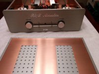
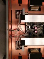
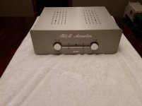
Well, 99% done...at last !!!!
(Will design the aluminum "volume gradation" ring to go around the knobs a little later)
I would like to take the opportunity to say a HUGE thank you to Salas, TeaBag, AndrewT (even if we sometimes had different points of vu, I respect what you bring to DIY community) and others who shared tips and all along the way.
You guys helped me more than I would have hoped.
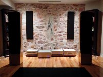
My DCB1 has the test board in and is now playing. Really impressive, very well balanced sound even if music has been playing for about an hour only. Tonaly, it is almost scary good...
Can't wait for the "burning" to work its magic...
Anyway, thanks a lot again and again. Now moving to "DCB1 resistors tryouts" thread as I will begin testing soon (starting resistors kit: 220R Shinkoh tantalums, 1M Riken Ohms, 220K Allen-Bradley @ less than 5% after drift).
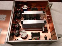
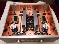
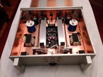
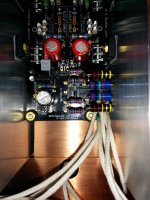
Here are a few pics.
Regards
Scorpion
(Will design the aluminum "volume gradation" ring to go around the knobs a little later)
I would like to take the opportunity to say a HUGE thank you to Salas, TeaBag, AndrewT (even if we sometimes had different points of vu, I respect what you bring to DIY community) and others who shared tips and all along the way.
You guys helped me more than I would have hoped.
My DCB1 has the test board in and is now playing. Really impressive, very well balanced sound even if music has been playing for about an hour only. Tonaly, it is almost scary good...
Can't wait for the "burning" to work its magic...
Anyway, thanks a lot again and again. Now moving to "DCB1 resistors tryouts" thread as I will begin testing soon (starting resistors kit: 220R Shinkoh tantalums, 1M Riken Ohms, 220K Allen-Bradley @ less than 5% after drift).
Here are a few pics.
Regards
Scorpion
Attachments
-
 IMG_20141019_224635.jpg465.1 KB · Views: 287
 -
 IMG_20141019_224706.jpg564.6 KB · Views: 289
 -
 IMG_20141019_224715.jpg702.6 KB · Views: 293
 -
 IMG_20141019_224724.jpg673.2 KB · Views: 280
 -
 IMG_20141019_224806.jpg473.7 KB · Views: 266
 -
 IMG_20141019_224820.jpg493.4 KB · Views: 169
 -
 IMG_20141019_230507.jpg389.4 KB · Views: 174
 -
 IMG_20141019_234251.jpg609.4 KB · Views: 187
Scorpion,
Very nice built on DCB1, what are you using for the 0.22uF/100uF for bypassing the led? What is the total capacitance you use on the power supply for each channel?
Thanks Skylab,
The LED bypass caps are Duelund CAST @ 0,33uF (birthday gift from my wife ). They are underneath the board and are clearly visible on prior pics I posted here.
Total capacitance is 20175uF per channel (2X Epcos Sikorel @ 10000uF + 175uF ClarityCap TC with 1.0 ESR)
Regards
Scorpion
Last edited:
- Home
- Source & Line
- Analog Line Level
- Salas hotrodded blue DCB1 build