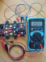
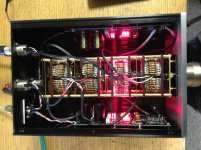
Well, I’m the seller than Myint64 refers ") . Attached are pictures of the relevant DCB1:
. Attached are pictures of the relevant DCB1:
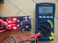
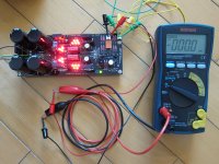
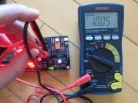
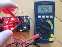
Rails - +10.05V, -10.06V
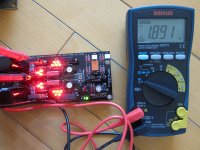
Rset - 1.88V, 1.89V
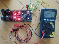
Offset - -0.3mV, -0.0mV
Idss - 9.9mA (not shown in the pictures)
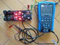
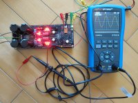
2 of the diagrams shows the output waveform at the 2 channels, when a 22kHz signal was injected at the input.
In terms of symmetry, offset and Idss, I believe this is a really nice DCB1.
. Attached are pictures of the relevant DCB1:Rails - +10.05V, -10.06V
Rset - 1.88V, 1.89V
Offset - -0.3mV, -0.0mV
Idss - 9.9mA (not shown in the pictures)
2 of the diagrams shows the output waveform at the 2 channels, when a 22kHz signal was injected at the input.
In terms of symmetry, offset and Idss, I believe this is a really nice DCB1
.Attachments
BTW, I find the Fluke infrared sensors very difficult to use, I just have difficulty figure out how to set the emissivity correctly.
A LM35A IC sensor connected to my DMM is much easier to use.
BTW thermal imaging is the real thing. Flir one for 4inch Iphone is the cheapest way to get into thermal imaging.
https://www.youtube.com/watch?v=IHQr6F7757c
Cwtim01 matched the MOSFETS also?
Didn't really match them cause I only had 4 pairs of 240/9240 to play with (from 2 set of Teabag full kits), I did curve trace them though to put the closer ones in pair, and then use the diodes to compensate the Vgs difference.
*If someone is perfectionist about matching the Verf LED gangs of 5, the best maniac party trick is to use a *12V battery, connect gate and source together in the specific 2SK170s that are going to feed those strings
Dear Salas,
In the scheme, as I interprete it correctly: Rs of 10 ohm does do the current limiting ? I'm not sure if I interprete this correctly.
So why not doing the following in the test-circuit for Vref LED: 10 ohm between G&S in stead of connecting the gate and source directly?
I understand that in you're way...you are making a constant current source, but I don't understand why not puting Rs of 10 ohm (like in the scheme) in between Gate and Source.
Last edited:
Dear Salas,
In the scheme, as I interprete it correctly: Rs of 10 ohm does do the current limiting ? I'm not sure if I interprete this correctly.
So why not doing the following in the test-circuit for Vref LED: 10 ohm between G&S in stead of connecting the gate and source directly?
I understand that in you're way...you are making a constant current source, but I don't understand why not puting Rs of 10 ohm (like in the scheme) in between Gate and Source.
That 1 or 10 Ohm is a test point resistor, just floats the whole by some mV, it does not current limit. G&S are already together above it.
How much difference in ccs current positive and negative is ok?
Been lurking through all the pages, before building my version on perf board ( am I the only one?? ). The big Fets are mounted on a separate heatsink and are connected by short wires.
After building the psu and the shunt regulator, I tried it out, and tried to measure the noise on the output, which was not the greatest success, I need a better scope for measuring the noise of this thing!!! Only at the most sensitive setting I managed to see some. This is by far the quietest power supply I have ever seen on my bench.
Did the original schematic first, with two 47 Ohm resistors in parallel for the ccs, and paralleled three times 10 Ohm to them later.
Measuring the voltage over the ccs resistors showed 1.567 Volts on the positive reg, and only 1,361 Volts on the negative side. That means 536 mA positive, and 466 mA negative.
Question: how close should the current between the two sides be??
Other question: What difference does the 0.22 cap make? In my first version I forgot to solder it in, did that later but could not measure any improvement. Perhaps some folks with better equipment can measure a difference?
Thanks for making all this information available. I am a quite experienced repair guy, but building something is great fun too!!
You could minimize the difference in running current per polarity to 5% i.e. 25mA in your case for more symmetrical heat distribution. By trying towards 0.2V more total VF on the negative side's LEDS triplet. Or by paralleling a resistor to the negative side now setting ones, maybe 15 Ohm.
The 0.22uF is minimal, its essentially an HF filter to the voltage reference only. You are measuring a largely non noise filtered regulator right now.
But people preferred it like that in the context of a line level non voltage gain client circuit. To filter it, also judge subjectively for yourself, and to see less rails noise (mainly on 24bit FFT test gear) it takes 100-1000uF 25V electrolytics vs the 0.22uF films.
Thanks Salas.
Have to try it through the setting resistor, because the leds measure extremely close, difference is in the mV's so that will not change anything. Will give it a try, with the calculator to compute the current.
Just realised I did not say anything about the sound. I already had a dcb1, running on a quick and dirty LM317/337 power supply with a transformer from a cd player. That already sounded so much better than any preamp I have had on my bench lately, that I decided to go all the way with it, but on a budget. So found a 2x12V transformer 2,08A for a fiver, salvaged a heatsink from an old amp. The rest unfortunately is new.
With this new power supply it just takes the dcb1 a step further in sounding relaxed, hot rodding brings it even more in control. As my heatsink is only 41 degrees now, I might take it a bit further to see where it ends...
- Home
- Source & Line
- Analog Line Level
- Salas hotrodded blue DCB1 build