
Cheers BigE. Did you connect power ov to chassis earth with the inverted diodes arrangement?
I used the arrangement from the F5Turbo article, substituting a 10 Ohm resistor for the thermistor -- just because I had a bridge, and I could screw the bridge to the chassis to provide a safe wiring point. I took PCB ground from the auxilliary +/G/- solder pads near the buffer circuit. The grounds from the rcas are routed as in my previous post.
The full ground path is: RCA -> pot -> Molex -> G -> ( diode bridge || 10 ohm resistor ) -> Earth
I looked on a scope. It is DEAD quiet.... the noise on signal pin to earth *goes down* when power is applied and the relay opens....about 0.5 mv.
I checked on the scope for difference from the previous version: which used G-> inverted diodes -> Earth.
There was no difference in noise between signal pin and earth.
BTW: DC offset is around 2 mv. Should I fool with the fets?
Last edited:
I just noticed an error in my DCB1 build when looking over the build pictures I posted. The transformer has the mains high tension wires crossing over the low tension output wires where they enter and leave it. This might account for the low level hum I'm getting. As Homer Simpson would say, Doh 
I'll correct it tomorrow and report back.
I'll correct it tomorrow and report back.
Both high and low tension sets are twisted which made me think I had a ground loop issue between the mains earth of the DCB1 and my power amps, this may still be the case but i'll try moving the DCB1 PSU wiring later on anyway to rule that out. I had hoped the diodes I ordered would have turned up by today but no luck. I might just wait until I get them before I do anything more to the DCB1.
What is the best way of twisting the two sets of low tensing wires Andrew? Options are 2 twisted twins running parallel. All 4 wires twisted together in a bunch or a platted weave of all 4 wires.
What is the best way of twisting the two sets of low tensing wires Andrew? Options are 2 twisted twins running parallel. All 4 wires twisted together in a bunch or a platted weave of all 4 wires.
A dual secondary with two bridge rectifiers has two sets of twisted pairs.
A centre tapped with one bridge rectifier has one set of twisted triplets.
If you convert a dual secondary to a centre tapped, then all 4 wires will be in a twisted quad until the centre tap becomes one wire, then a triplet thereafter.
For low level signal wiring I have played with star quad using cat5 and it seems to be completely impervious to fields from transformers and mains cabling. I could not detect any increase in measured hum at the amplifier output when waving the 2.8m star quad around the various mains components lying spread about on the floor. I even laid the toroid on top of the star quad at one point.
Thanks Andrew, it's dual secondary to centre tapped but the two sets of secondary wires are twisted into two pairs. I will move the transformer and a use star quad twist, hopefully that will cure it. The hum is low, I have to put my ear very close to the speaker drivers to hear it but I am fussy about hum and it does degrade sound quality.
chassis
Can anyone advise if this case provides sufficient heat sinking for the 200ma hotrodded blue board:
Galaxy 288 (3mm Front) - Compact with Quasi Heatsinks - Chassis
Would it be better to go with the 10mm aluminum front or even the larger, max vented model:
Galaxy 388 (10mm Front, Max Vented) - Compact with Quasi Heatsinks - Chassis
Thanks!
For 200mA even the first one is fine with the Mosfets just bolted to the chassis floor.
The second one is a nicer box with thick front panel and many more top lid perforations to can see the LEDs glowing. It would really matter for ventilation at 600mA+ CCS and dedicated sinks, no floor mount is enough anymore.
The second one is a nicer box with thick front panel and many more top lid perforations to can see the LEDs glowing. It would really matter for ventilation at 600mA+ CCS and dedicated sinks, no floor mount is enough anymore.
Clearly far too professional looking to be considered diy though
Just for you, so you can't say that

Just testing
For 200mA even the first one is fine with the Mosfets just bolted to the chassis floor.
The second one is a nicer box with thick front panel and many more top lid perforations to can see the LEDs glowing. It would really matter for ventilation at 600mA+ CCS and dedicated sinks, no floor mount is enough anymore.
Thanks, Salas! I may go with the larger one to later add a source selector.
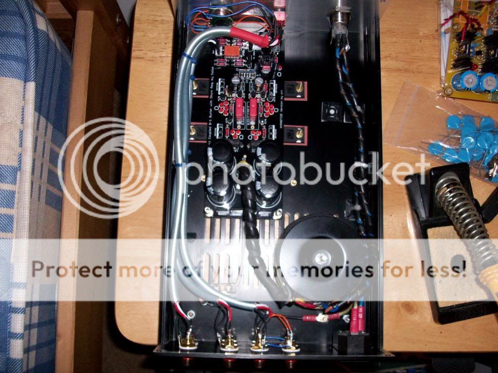
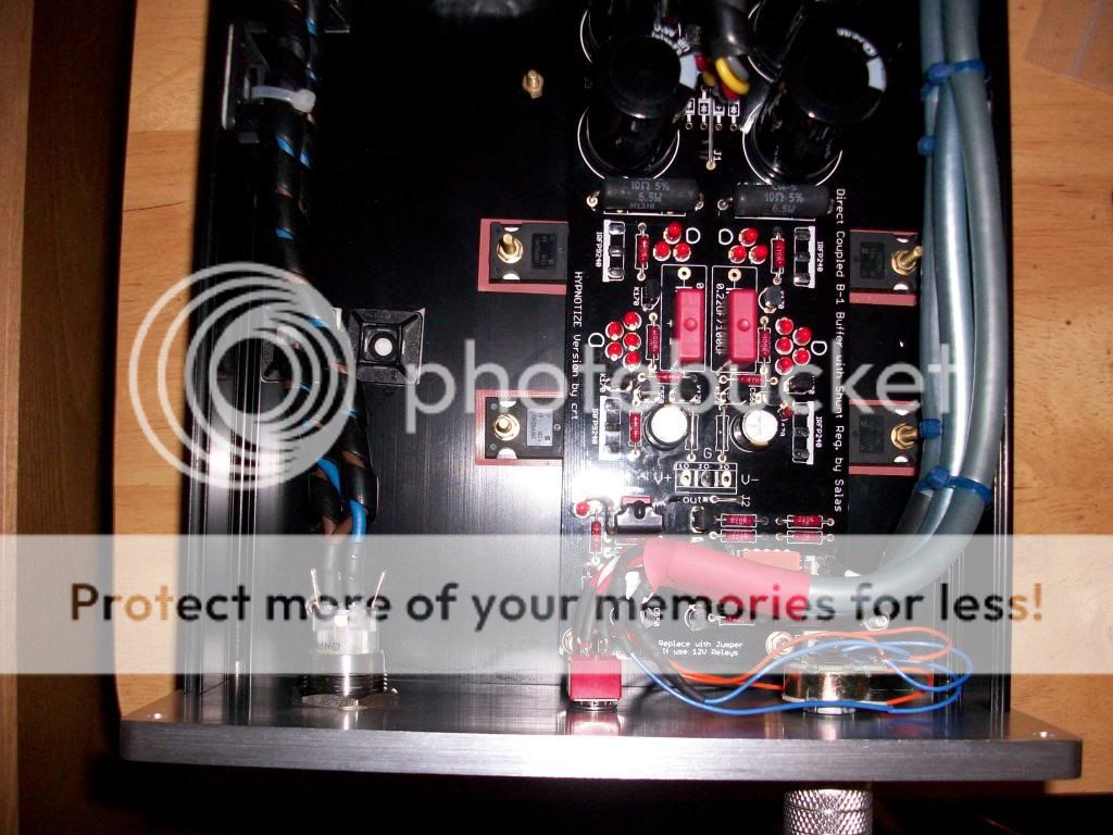
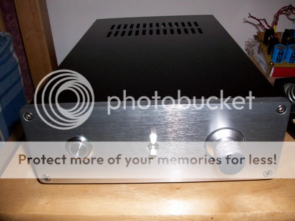
Success! I finally got my partially hot-rodded DCB1 completely finished today.
It now has a 20K DACT stepped attenuator and a silver plated contact miniature toggle switch fitted to the front panel, two switchable inputs and two variable outputs.
I used microphone cable to carry both channels which reduced the internal wire runs and seems to work very well. I also fitted an ground breaker but it made no noticeable difference and as it's extremely quiet now I removed it (after I took some pictures) and just connected 0v to a chassis stud.
I also arranged the PSU better and sleeved the wiring. I'm now a very happy chappie indeed. It sounds brilliant and looks the part too.
Huge thanks to Salas, shoom, teabag, Andrew T and everyone else who helped.


- Home
- Source & Line
- Analog Line Level
- Salas hotrodded blue DCB1 build