View attachment 388645
5 ohm shunt resistor. Can I solder 10 ohm across ? I do not think it is hot with the 5 ohm. 20,5 vdc on input
Will not do that ! Retifiers are a bit hot allready.
Sure can, with those sinks, I think 1.5-2R will get you in the zone.I use 2R and probably a bit less sink.
But adding 10R will bring more current. Just weld them to the other resistors, so can change easily.
But then I will need heatsinks on the diodes to ?
Up to 1A CCS the TO-220 diodes will stand the tests. But help them later for long run reliability.
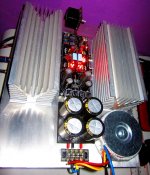
Erlend, where did you get that case?
I will send you a link in a mail tomorrow. They are very cheap. I got them from Along on ebay .
I will send you a link in a mail tomorrow. They are very cheap. I got them from Along on ebay .
This one?
DIY Kit, Audio power amplifier items in along1986090 store on eBay!
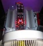
I was so happy when all led light up in the morning, I measured voltage drop on CCS resistor by 1.4V & 1.5V and Vout -10.3V & 10.2V eventhough i'm still using 12V transformer 
but after 5 minutes the upper led stop working and i re-measure the voltage as shown on attached picture. What could probably cause this malfunction? I also can not hear any click on the relay, while regulator seems working, what need to be checked?
but after 5 minutes the upper led stop working and i re-measure the voltage as shown on attached picture. What could probably cause this malfunction? I also can not hear any click on the relay, while regulator seems working, what need to be checked?
Attachments
Check those extinguished team of LEDS one by one with DMM in diode mode to find which one could have died, without need to pull them out first. If your DMM don't have the voltage to light an LED use 9V battery and 1K resistor in series. If you find any bad, replace and power up. If problems continue or you did not find any bad, check that side's reg area K170s with DMM in Ohm for about 40-50 Ohm each from drain to source pins. If open or short, replace. Try power up. Check BC560 for Vbe. If showing nothing, replace. Try power up. If no cigar, check IRFP240s for Vgs. If not showing something like 4V but zero or too much, replace.
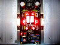
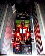
when I got back home, i turn on this dcb1 again and all leds are working without any changes yet. When I touch bottom plate of irfp, i don't feel any heat. While ccs resistor is very hottt, i can't touch it more than 5sec. Then i put a fan, ccs resistor is just a bit warm and it's been 2 hours that all leds are still working. I assume this ccs resistor is the culprit. below some measurements that i got:
- Vout ; +10.3V but neg rail is drifting between -11.8V until -12.2V
- Vdrop ; +rail 1.5V, -rail 1.4V
- if I calculate heat dissipation on CCS resistor ; 1.4V^2 / 2.7R = 0.8W only. Do i calculate it properly? this dale should be rated 6.5W
I'll change ccs resistor to draloric 10R rated @7W (hopefully the rating is correct) in the morning and hopefully is not too hottt, while now i'll enjoy the light show
Attachments
Last edited:
Maybe a bad solder joint on that resistor or on some MOSFET, or some weak end cap to element fusion doesn't take the heat in one setting resistor? Neg rail drifting is a sign that something is still playing up. Check that all MOSFETs show Vgs and all BJTs show Vbe. When you will change those CCS resistors, rework the solder joints of all MOSFETs after they are bolted down. Bolting can stress solder joints. Make sure that the MOSFETs do press their backs well against the pads and chassis.
P.S. Keep the new resistors off contact to pcb by few mm so air circulates around them.
P.S. Keep the new resistors off contact to pcb by few mm so air circulates around them.
change ccs resistor to 10R, ccs resistor is hot but i still can touch it, no wonder 2R7 is very hottt. it's been running for 1hour and do some measurements:
- Vout; +10.27V, -10.41V
- Vdrop; +rail 1.85V, -rail 1.67V
- Vgs; IRFP240 ccs 4.04V, reg 3.96v, IRFP9240 ccs 3.99V, reg 3.88V
isn't it great I have another 6pcs 10R, will make a ladder with 4 ccs resistor on each side
Salas, this is my first discrete build, get so much learning for my next project
- Vout; +10.27V, -10.41V
- Vdrop; +rail 1.85V, -rail 1.67V
- Vgs; IRFP240 ccs 4.04V, reg 3.96v, IRFP9240 ccs 3.99V, reg 3.88V
isn't it great
I have another 6pcs 10R, will make a ladder with 4 ccs resistor on each side Salas, this is my first discrete build, get so much learning for my next projectAttachments
Last edited:
Merry Christmas everyone,,
I finished my DCB1 this morning and may have an issue.
there is almost no DC offset meaured, but when I measure vout I get +14.4 and -14.2.
this I measured between v+ and ground and V- and ground on Tea Bag black version.
AC in is 12 v on each side. all LEDs light up and nothing is hot, although I left it on only a few minutes to measure voltage.
Since the forum seems to suggest 10 volts or so is a normal level, what would be wrong in mine.
I can think if 3 things:
1. I did not have mur 820 diodes so I used something similar I had on hand from a peter daniels kit I believe, which are labeled u860. would this have an impact?
2. I did not meaure voltage across my LEDs, just used them all from the same batch and I assumed they were 1.8 volt leds but could have been something else. I has been a long time since I purchased them and cannot remember their voltage. Would a different led voltage stream cause me to get vout at this high level?
Would either one or two give me this huge voltage level.
across 10 ohm five watt resistor (hot rod version) I have 1.5v on left side and 1.9v on right side.
3. I am measuring V out at wrong place.
Anythoughts or ideas appreciated. With this voltage level do not want to hook it up to my F5 yet as I do not want to ruin anything till I get DCB1 correct.
Thanks any suggestions or ideas
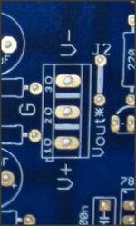
3. Make sure you measure where the attachment shows.
2. Unlikely that red LEDS can get the Vref so high but measure a couple from that batch to know.
1. Very unlikely to be the root of a problem.
Let us know about those results.
Merry Xmas.
2. Unlikely that red LEDS can get the Vref so high but measure a couple from that batch to know.
1. Very unlikely to be the root of a problem.
Let us know about those results.
Merry Xmas.
Attachments
Finished testing with several iterations on-off and let it run for hours to check it's stability after changing ccs resistor with 5pcs 10R ladder. I think that I'll keep this setup since both heatsinks and base plate is warm enough. below some measurements:
- Vout; +10.18V & -10.20V
- Vcss; +rail 1.55V, -rail 1.12V
but i still have problem, relay is not working. I make some measurements on relay circuit:
- V on in4001 : 1.7V (i put in4002 since no any in4001 stock)
- V on 10K : 11.6V
- V on 47K : 2.6V
then i try connect bc517 base&emitter and relay clicks with 4.2V between in4002.
- Why relay circuit does not work on default?
- If i keep shorting bc517 base&emitter, is there any impact for long life cycle?
Attachments
Find a combination to make -rail set resistor about 1.45R total so you equalize to the +rail current which is higher due to lower Vgs difference and possibly little lower Vf. 1.55V/2R=0.775A when 1.12V/2R=0.56A. Does BC517 show any Vbe? Maybe a burned 517 that needs changing?
- Home
- Source & Line
- Analog Line Level
- Salas hotrodded blue DCB1 build