Nigel - I agree entirely that the purpose of a valve amp is to add distortion, but all distortion is not equal, musically speaking. The distortion from the exponential characteristic of a diode is very nasty, and very ugly sounding. Also, if you put together a well designed triode valve common cathode amp stage, and an equivalently well designed common emitter transistor amp stage, the amount of distortion the transistor circuit generates is very large compared to the triode.Why would you want to reduce distortion? - this is a valve amp, it's whole reason for been there is to give distortion.
So 10% THD from a triode valve can sound very nice indeed, while 10% THD from a transistor amp will sound nasty - probably enough to make you want to stick your fingers in your ears and run away. This is the whole reason why so many electric guitarists still pay lots of money and expend lots of sweat hauling big, hot, heavy, electrically inefficient tube amps around.
This characteristic of semiconductor diodes is why solid state fuzz boxes built around clipping diodes or (transistors used as diodes) never sound as sweet as a good tube amp. And that's also why solid-state transistor-based amps evolved to use huge amounts of negative feedback - it's the only way to tame the nasty distortion from the exponential characteristics of all those transistors.
Using tons of negative feedback keep everything linear and distortion free right up to the output limits of the amp, but when you do hit those limits and drive the amp beyond them, all hell breaks loose, and the distortion gets really harsh and really nasty in a hurry. Which is why transistor amps are very well suited to applications where you want negligible distortion and the amp never gets overdriven - but they're not at all good for applications where overdriving is a routine event.
The reason why semiconductor diodes sound so bad, by the way, can be found in their exponential current-voltage curve, and the Taylors expansion of that exponential function: it contains every harmonic, both odd and even. Put a sine wave through a diode, and you get a whole slew of harmonics, including the very nasty sounding higher order odd harmonics.
I grew up with semiconductor circuits, and I was amazed the first time I looked at a set of triode (valve) curves - they are so much more linear than a transistor! If I didn't know better I would have thought the valves were the "new and improved" technology, and the transistors the old historical left-overs!
(Of course a quick glance at the curves doesn't show all the other good reasons why tubes eventually were almost completely replaced by solid-state devices in most electronic circuits.)
-Flieslikeabeagle
The distortion from the exponential characteristic of a diode is very nasty, and very ugly sounding.
Take a look at the distortion spectra here:
DIY Test Equipment for Audio and Ham Radio Enthusiasts (jackinnj's post in the comments)
which uses series LEDs for bias.
Or here:
http://www.diyaudio.com/forums/diya...se-thoroughly-modern-tube-phono-preamp-3.html
which uses LED bias in two cascades stages. No feedback loops in either or these designs.
Where's that nasty and ugly distortion?
That's the misleading part - remember, this is an exponential curve. Therefore a +26 mV change in voltage causes a 272% increase in current through the diode - no matter which part of the curve you're on. Meantime, a -26 mV change in voltage causes the current to drop from its initial value by only 63.2%. [It drops from its initial value (100%) to 1/e of that amount (36.79%), which is a drop of 63.2%.]Flies, remember that you're operating on the steep part of the exponential which in fact is quite close to linear.
So you put in a symmetrical sine wave (equal positive and negative voltage swings of 26 mV), and got out an incredibly distorted wave - positive peaks are nearly five times bigger than negative peaks, 272% vs 63%!
Flat with frequency, yes. So it will flatten the frequency response. Unfortunately, it introduces harmonic distortion instead of frequency distortion. And harmonic distortion is much more obnoxious, particularly theHolding the cathode at AC ground (or just a couple ohms away from that) with a low and flat impedance is beneficial
broad-band, multiple harmonics you get from an exponential curve.
It might reduce it a little, yes. Instead of a sharp initial current spike that slowly trails off as the capacitor charges, you get a square-wave step change. Unfortunately both those waveforms (cap charge current and step function) have plenty of high frequency components, which will cause the audible thump the OP reported hearing.You're right about the change in bias - that is indeed a transient. The LED removes the charge/discharge of the electrolytic from the transient and will reduce it but not eliminate it.
To reduce the thump, all you can do to slow down the rate at which the cathode voltage changes. That won't reduce the size of the DC swing either, but it will spread it out over a bigger amount of time, which means the corresponding frequency components in the transient are moved down to lower frequencies, which means they won't make it through the coupling cap to the next stage.
Do you happen to have a different equation you can point to for LED's? The equation I quoted is independent of the actual band-gap of the material, and so I wasn't expecting it to be substantially different for LED's (which are made from materials with higher band gaps). I have seen some books throw in a fudge factor (sometimes called alpha), but it it seems to represent minor amounts of impurities in the semiconductor material rather than anything to do with the bandgap, and typical values of alpha are close to 1.0, so it doesn't change anything we've discussed here much.edit: The numbers you give are for silicon, not for the semiconductors used in opto.
Any way you look at it, the size of the problem is equally bad. Yes, increasing it by 300% causes only a +26 mV change - but a reduction of only 63% will cause the same -26 mV change! As described in my first paragraph, you get a horribly distorted wave, with wildly unequal positive and negative swings. THAT is the problem!This part, "a voltage increase of only 26 mV across a semiconductor diode will nearly triple the current through it" makes my argument for me if you turn it around- tripling the current only changes the voltage by 26mV!
All you have done by inverting my statement is replaced an exponential relationship [I is proportional to the exp(V)] with its mathematical inverse function, which is logarithmic (the voltage across a diode is proportional to the logarithm of the current through it). Unfortunately, a logarithm is just as far from being linear as an exponential is.
If I have time later tonight I'll run some numbers through a spreadsheet and post a graph here - that might make the extent of the distortion problem clearer.
-Flieslikeabeagle
Where is that 272 percent increase in current through the diode coming from? The 100k (or whatever it is, I forget, too lazy to go back in the thread and look) resistor in series with the plate?That's the misleading part - remember, this is an exponential curve. Therefore a +26 mV change in voltage causes a 272% increase in current through the diode - no matter which part of the curve you're on. Meantime, a -26 mV change in voltage causes the current to drop from its initial value by only 63.2%. [It drops from its initial value (100%) to 1/e of that amount (36.79%), which is a drop of 63.2%.]
Googling for tube load line brings up this fun little article:
How to "Screw Around" Your Tube Load Line
It's hard to see how you're going to get a 272 percent increase in diode current.
So you put in a symmetrical sine wave (equal positive and negative voltage swings of 26 mV), and got out an incredibly distorted wave - positive peaks are nearly five times bigger than negative peaks, 272% vs 63%!
You have it backward. If the LED is in the cathode and you apply the signal to the grid, the current swing (for this example, let's stick with 0.1mA) will induce a voltage swing of 0.5mV or so on the diode. Try doing this experimentally- I have, and looked at the resulting spectrum.
The voltage induced across the LED is almost undistorted exactly because it takes a lot of current swing to make a small voltage swing; if you prefer doing this theoretically, you can sim it or even plug in the current swing into the exponential relationship and see how tiny the voltage induced across the diode is. From a power series POV, the linear term dominates because the variable in the numerator is small, so higher order terms vanish.
More experimental proof is in the spectra I linked to. And as Ben pointed out, you can't possibly have a 272% current swing- 10% will take the plate to clipping in most voltage amplifier circuits.
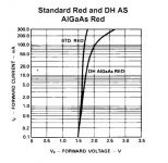
By way of illustration, here's the If vs Vf for an HLMP6000, a cheap, readily available red LED (I've got a few hundred of these in my parts drawer, bought at Mouser). For a current swing of even a milliamp or three, the change in forward voltage is minuscule. You have to be swinging several dozen milliamps before the curvature becomes an issue.
Attachments
Ben, you're absolutely right, in an actual audio circuit you will not get that big a percentage increase. My point was that it only takes 26 mV change across a semiconductor diode to cause that absurdly enormous change in current through it. It takes even less to cause "only" a 100% swing in current, and even less to cause "only" a 50% swing in current.It's hard to see how you're going to get a 272 percent increase in diode current.
Let's look at some smaller signal swings to see how things change. If you applied, say, 10 mV signal swing to the diode instead, the percentage change is exp{(+/-10)/(26)}, This works out to +147 % on positive input half-cycles, and -32% on negative half cycles. Still very asymmetrical, very distorted.
If you go still smaller and applied only 5 mV across the diode, the percentage change is exp{(+/-5)/(26)}. This works out to +19% and -17.5%. Now we can see that the positive and negative swings are getting closer to equal, i.e. the amount of distortion created by the diode is being reduced.
Let's go still smaller. Get down to 1 mV, and you only have about a +4% increase in current on positive half-cycles, and almost the same -4% decrease in current on negative half cycles. So at this low voltage, the diode is almost linear and creates little distortion.
So these numbers say that very small AC voltages across a semiconductor diode are okay, but the effect of diode nonlinearity shows up rapidly if you drive it with more than a few mV.
That's one of the reasons why low distortion solid-state amps have evolved to have very high open-loop gain, and then lots of negative feedback added around the amp. If an amp has an open-loop gain of 1,000,000 (typical for many cheap op amps), and it's putting out a big fat 10 V rms signal, the actual input voltage going into the first semiconductor device is only (10 volts/1,000,000) - that's only 10 micro volts, or 0.01 mV! So there is not much distortion to start with, and the negative feedback pushes it down some more, and that's how you get those crazy low 0.001% THD numbers out of some solid state amps.
As you suggest, things will be a little different in a tube guitar amp. Guitar pickups can put out initial transient peak voltages that are quite large - recently I saw an oscilloscope trace showing 6 volts(!!) peak from a humbucker pickup when a full six-string chord was played hard. Average voltage from a pickup is much, much lower - I've heard the number 100 mV bandied around, but it is a very rough figure, obviously, as it varies with pickup type, string gauge, playing technique, and how many seconds it's been since the string was first struck.
So here's the question to which I don't yet know the answer - if you apply a sine wave with 100 mV peak voltage to the grid of an 12AX7, and bias the cathode to ground via, say, a red LED, what is the actual voltage swing across the diode? We know the answer will be less than 100 mV, because the tube's cathode resistance uses up some of that 100 mV swing within the tube itself. Only a fraction of the total 100 mV ends up across the LED.
But how much voltage exactly actually ends up across the LED? Is it 26 mV (very bad)? Is it only 10 mV (not so bad)? Is it even less than that? I don't know the answer. And right now I don't have a suitable power supply, tube socket, and a few other components needed to make that measurement.
If we knew that number, we could make an estimate of the amount of distortion (waveform assymmetry) that the LED would add to the audio signal.
Anyone out there with a signal generator, oscilloscope, breadboard, and spare 12AX7 and red LED want to make that measurement and report what they find?
-Flieslikeabeagle
Anyone out there with a signal generator, oscilloscope, breadboard, and spare 12AX7 and red LED want to make that measurement and report what they find?
-Flieslikeabeagle
I've done it. That's how I got the AC impedance of LEDs. See my article on The Red Light District amp on the test setup and results.
See the curves in the post above and the actual experimental results I've linked to. Where's the distortion from the LEDs? Ain't there.
Again, you're thinking of this backward- you aren't applying a voltage to the LED, you're applying a voltage to the tube. The tube in turn swings a current (the swing depending on the load and the applied signal). That current swing induces a voltage swing on the LED. If the current swing is 0.1mA, the voltage swing is 0.5mV or (for the HLMP rather than the cheap surplus LEDs I tested) even lower.
So here's the question to which I don't yet know the answer - if you apply a sine wave with 100 mV peak voltage to the grid of an 12AX7, and bias the cathode to ground via, say, a red LED, what is the actual voltage swing across the diode?
i = gm * Vin. For a gm of 1mA/V (typical for 12AX7), the current swing is .1mA peak- the number I've been using in the examples. So the cathode voltage swing is 5mV for a cheap LED, a bit less for a star like the HLMP.
edit: this is true for a constant plate voltage. If the plate voltage swings (i.e., you have a load resistor) that number gets smaller. In the limit of a CCS load, the current swing is zero, and the voltage swing across the LED is no longer minuscule, but totally absent.
Do you happen to have a link to the schematic? Without that, and without knowing the signal level across the LED, there isn't enough information to draw any conclusions.Take a look at the distortion spectra here:
DIY Test Equipment for Audio and Ham Radio Enthusiasts (jackinnj's post in the comments)
which uses series LEDs for bias.
Lessee, looks like your input transformer has a 1:10 step up ratio, and input signal from your moving-coil cartridge is what, 100 uV? So the input voltage to the first stage is around 1 mV. The actual signal swing across the diode is even less, as you pointed out, due to the tubes cathode resistance. So it's no surprise that the LED doesn't contribute any significant distortion - the signal level is extremely low, much less than the 26 mV value of the diodes Vt. (Some of the stuff in my previous post is relevant here.)Or here:
http://www.diyaudio.com/forums/diya...se-thoroughly-modern-tube-phono-preamp-3.html
which uses LED bias in two cascades stages. No feedback loops in either or these designs.
Where's that nasty and ugly distortion?
Okay, that explains the first stage of your circuit. But what about the second stage in your design?
That one had me thinking hard for a minute or so. Then I noticed that your LED bias current was 10 mA - and I think that may provide the answer to your question about the "missing" distortion.
First, a little background. It's been maybe 25 years since I first read about op-amp circuits that used the exponential characteristic of a semiconductor diode deliberately, to create either a logarithmic or exponential of the input signal (nowadays it would probably be done in software in a microcontroller). There were many situations where either a log function or an exponential function could be useful - for instance, a log amp driving a linear voltmeter is a good way to get a decibel readout, and an exponential amp driving a voltage controlled oscillator is a good way to turn an analog control voltage into the frequency of a musical note.
Anyway, some of the references I read studied the exponential characteristics of diodes and transistors, to find out just how wide a range of currents they could accurately cover. My memory isn't entirely trustworthy after this long a period, but what I recall is that the exponential/logarithmic characteristic is very accurate over a range of several decades in current - typically from around 0.1 uA to around 1 mA or so. At much lower currents, the effect of leakage currents would creep in and spoil the true exponential behavior. And at much higher currents, the (linear) ohmic resistance of the diode would begin to swamp the exponential characteristic of the junction, making the diode less exponential and more linear.
So my guess is that the rather high 10 mA bias current through your second stage cathode LED - ten times higher than that 1 mA limit of exponential behavior - has taken that LED beyond the exponential part of its characteristic curve, and into the fairly linear ohmic part. And that's why the second LED isn't contributing much harmonic distortion.
If I'm right, your two LED's fell neatly on two sides of the disaster area, by sheer chance! In the first case, the signal voltage is low enough to avoid excess distortion. In the second case, the bias current is high enough to carry the LED out of its nonlinear region.
Going back to the first post in this thread, I still don't think an LED is a good choice for cathode biasing the first stage of an electric guitar amp. The signal voltage from the guitar is high enough to cause lots of diode distortion (way, way more than the roughly 1 mV your MC preamp's input tube sees), and the bias current of the first stage tube is not high enough to push the diode beyond its exponential range and into the nearly linear high-current range.
-Flieslikeabeagle
That part doesn't require measurements. All you have to do is differentiate the exponential equation and solve for dV/dI...I've done it. That's how I got the AC impedance of LEDs.
IIRC, the answer is that the AC resistance in ohms equals (26/Idc) where Idc is the bias current in milliamps, and the 26 comes from the diodes Vt.
Read my last post...I was writing it while you posted this one. I think you got lucky in your choice of operating conditions.See the curves in the post above and the actual experimental results I've linked to. Where's the distortion from the LEDs? Ain't there.
Your description would be perfectly accurate if the tube has infinite cathode resistance (i.e. it's a pure current source at the cathode). My way (influenced by my solid state background) would be perfectly accurate if the transistor has zero emitter resistance (i.e. it's a pure voltage source at the emitter).Again, you're thinking of this backward- you aren't applying a voltage to the LED, you're applying a voltage to the tube. The tube in turn swings a current (the swing depending on the load and the applied signal).
Reality is somewhere in between your description and mine - tubes have a finite cathode resistance, transistors have a finite emitter resistance.
In other words, the tube cannot swing a current without also having a corresponding change in voltage from its grid to its cathode - and that change in voltage appears directly across the LED, causing the distortion.
Okay, if it's 5 mV, we can estimate the extent of diode nonlinearity. Theory says that the positive swings cause a change of current by a factor of exp(+5/26), negative swings by a factor of exp (-5/26).That current swing induces a voltage swing on the LED. If the current swing is 0.1mA, the voltage swing is 0.5mV or (for the HLMP rather than the cheap surplus LEDs I tested) even lower.
That's +21.2% and -17.5% respectively. Take the ratio of those two numbers, and you see that the positive swings are 21% bigger than the negative swings. The waveform is markedly asymmetric, meaning that there will be quite a lot of harmonic distortion caused by the LED.
Exactly how much, I can't tell you off the top of my head. The Fourier series of exp[A sin (x)] is a truly nasty thing to try to calculate, so I won't even bother...that's why I used a series approximation when I worked on the problem back in the 1980s. But with a 21% waveform asymmetry, it's probably reasonably accurate to assume a ballpark figure of 10% harmonic distortion or so (enough distortion components to increase positive half-cycles by 10% and decrease negative ones by 10%, causing the 20% difference).
Off to hang out with my sweetheart for a while - the joys of esoteric electronics online discussions are not as strong as the joy of being in the same room with her!
-Flieslikeabeagle
Thanks for that article, by the way. Resistive load lines are old friends with me, but vacuum tube design is still new and exciting, and there is a lot I don't know about tubes.Googling for tube load line brings up this fun little article:
How to "Screw Around" Your Tube Load Line
Life is simpler with transistors - the collector voltage has almost no effect at all on the collector current, so it's easier to calculate bias currents and voltages. You can do a good job without ever seeing the curves for the transistor.
But with triodes, both the grid voltage and the plate voltage affect the plate current quite a bit, so things are more complex - and graphical solutions laid out on top of the (nonlinear) tube curves are the only practical way to get a workable answer.
As for pentodes, I'm still struggling my way through understanding how to bias them. There are so many interacting parameters to worry about - plate voltage, screen voltage, plate current, screen current, grid voltage - yikes!
-Flieslikeabeagle
The equation you keep using is for silicon diodes, not LEDs. If you differentiate the wrong equation, you'll get wrong results. It's not terribly important, the curves are qualitatively the same, but if you want to do it analytically rather than experimentally, you need to plug in the right constants and equations. Given the variables, I took the trouble to actually set up and measure- again, see the Red Light District article. Also, take a look at the actual experimental If vs Vf graph I posted. Since you're familiar with load lines, you should easily be able to determine the voltage swing from a given current swing- the slope is pretty darn high (i.e., for a given current swing, the voltage doesn't vary much- a battery would be proud!) and there's not much curvature.
The schematic for the ImPasse was in AudioXpress, so I can't reproduce it here. The cathode bias was two red LEDs in series for a 6SN7. Same sort of biasing scheme and results shown in the standard text "Valve Amplifiers" 3rd edition (p183. and pp558-559). Note that Jack also reproduced spectra for 20V out (which is 1V in). The distortion spectrum is quite clean and corresponds nicely to 6SN7 distortion results published by others.
At a certain point, you can't attribute a successful circuit tool to "luck."
Oh, yes, since we like 12AX7s, look at the spectrum in this post, which is a 12AX7 with LED cathode bias:
http://www.diyaudio.com/forums/tubes-valves/164920-guess-tube.html
Music Lesson
Ummm, did it not at all occur to you that I was posting simply for the sake of the truth? That what a guitarist wants with a cap on the cathode has nothing to do with anything a clean audiophile preamp has to say about things?
I was simply posting to keep irrelevancy out of the responses that the OP had to wade through for a solution to his problem.
But my doubts about that statement have little to do with me.
Anyway, moving right along . . .
But then you go and blow it:
Even harmonics are very musical. That's what makes a violin different from a flute.
Especially the second harmonic. The second harmonic is one of the biggest components of the "electric guitar" twang that makes the difference between a guitar amp and a transistor amp (of any kind).
Tubes are wonderfully well suited to producing the second harmonic because EVERY tube has a gain that decreases as one goes further negative on the signal grid. It is extremely difficult to slant a load line so that positive and negative excursions are equally large at the plate for a sine input. That's one big reason that audiophile tube amps are very expensive.
On the other hand, it is trivially easy to bias a tube so that it produces a pronounced second harmonic -- the very thing that makes the "signature" electric guitar sound. It is not at all ugly. it is incredibly musical and satisfying. The waveform does not flatten out suddenly, it simply goes lopsided with respect to the center line. This has the effect of mimicking the waveform of a violin, which is somewhat of a sawtooth, by putting a large lobe on only one side of the zero crossing with the ripples of the remaining harmonics too small to ruin that essentially saw shape.
So it isn't really accurate to say that "harmonic distortion" is in any way "obnoxious" much less "much more" so. It depends on which harmonics we're taling about. Smooth second harmonic? Sweet. Very sweet.
That's what you get from having a different gain on the positive side of the wave from what you have on the negative side.
In a "clean" guitar amp: beautiful.
And after the wave starts clipping? It's much more musical than what you get from transistors because you also have this second harmonic lopsidedness contributing to the distortion products, skewing everything toward the EVEN side of the spectrum because that larger lobe clips sooner than the other side of the wave does, dividing into other EVEN harmonics.
But it depends, too, on the proportions. Mix pure equal sine waves (transposed to be in the same octave) at fundamental and third harmonic (which is the first odd harmonic and also the musical "fifth" of a chord, ratio 3:2) and you get the earliest hint of the coming square wave that is the sum of all odd harmonics. (Do an algebraic sum on graph paper and see this.) But two flutes playing at the interval of a perfect fifth sound very musical. Add in the fifth harmonic (the next odd one, also the musical "third" of a major chord, ratio 5:4) and the resemblance of the result to a square wave is even more pronounced. Yet that result is simply the three notes of a major chord--a wonderfully musical sound (to us, anyway; it was a "dissonance" in 600 A.D.) Key here is that the lobes are all still rounded, and there are no sudden changes of direction with the accompanying sharp edges and high frequency components. BUT (and here's a big "but"), play that same major triad in the bottom octave of the tuba, and you'll begin to understand why transistor amps and their odd harmonics sound so bad. The harmonics being generated from the sum and difference frequencies and THEIR sum and difference frequencies are producing many higher harmonics that are still well within the range of hearing. Ouch!
On the other hand that tuba trio is nothing like hearing all the strings in the orchestra playing the same note in octaves, which is a series of even harmonics (1, 2, 4, 8, 16) and sounds lush and full and CONSONANT (even though each individual string is rich in higher harmonics).
So, to summarize: it's not a question of whether "harmonic" distortion is a weakness in a musical instrument amp. It's a question of WHICH harmonics are creating the distortion, and in what proportion.
Odd harmonics, strong higher orders? Duck.
Even harmonics, tapering higher orders? Musical bliss.
See the difference?
BTW, the reason that a synth keyboard needs a clean amp and doesn't sound as good through a guitar amp as a guitar does is that its wave is already loaded with higher order harmonics, odd and even. A guitar, while nothing quite as pure as a flute (i.e., sine wave), is still a relatively "clean" waveform as compared to other instruments.
Why do I doubt the validity of this little introduction?"I don't want any part of the little, erm, manhood contest going on between SY and tubekit, but I'll point out that . . ."
Ummm, did it not at all occur to you that I was posting simply for the sake of the truth? That what a guitarist wants with a cap on the cathode has nothing to do with anything a clean audiophile preamp has to say about things?
I was simply posting to keep irrelevancy out of the responses that the OP had to wade through for a solution to his problem.
But my doubts about that statement have little to do with me.
Anyway, moving right along . . .
True so far. And yes, this is also true for transistors, particularly when they are overdriven. And yes, those higher order odd harmonics are very especially noxious and nasty when they hit the ears."Put a sine wave through a diode, and you get a whole slew of harmonics, including the very nasty sounding higher order odd harmonics."
But then you go and blow it:
Without commenting on that last, excised phrase about the multiple broadband harmonics of an exponential curve, there is misinformation in the quoted part that needs clarification."So you put in a symmetrical sine wave (equal positive and negative voltage swings of 26 mV), and got out an incredibly distorted wave - positive peaks are nearly five times bigger than negative peaks, 272% vs 63%!"
Flat with frequency, yes. So it will flatten the frequency response. Unfortunately, it introduces harmonic distortion instead of frequency distortion. And harmonic distortion is much more obnoxious . . ."
Even harmonics are very musical. That's what makes a violin different from a flute.
Especially the second harmonic. The second harmonic is one of the biggest components of the "electric guitar" twang that makes the difference between a guitar amp and a transistor amp (of any kind).
Tubes are wonderfully well suited to producing the second harmonic because EVERY tube has a gain that decreases as one goes further negative on the signal grid. It is extremely difficult to slant a load line so that positive and negative excursions are equally large at the plate for a sine input. That's one big reason that audiophile tube amps are very expensive.
On the other hand, it is trivially easy to bias a tube so that it produces a pronounced second harmonic -- the very thing that makes the "signature" electric guitar sound. It is not at all ugly. it is incredibly musical and satisfying. The waveform does not flatten out suddenly, it simply goes lopsided with respect to the center line. This has the effect of mimicking the waveform of a violin, which is somewhat of a sawtooth, by putting a large lobe on only one side of the zero crossing with the ripples of the remaining harmonics too small to ruin that essentially saw shape.
So it isn't really accurate to say that "harmonic distortion" is in any way "obnoxious" much less "much more" so. It depends on which harmonics we're taling about. Smooth second harmonic? Sweet. Very sweet.
That's what you get from having a different gain on the positive side of the wave from what you have on the negative side.
In a "clean" guitar amp: beautiful.
And after the wave starts clipping? It's much more musical than what you get from transistors because you also have this second harmonic lopsidedness contributing to the distortion products, skewing everything toward the EVEN side of the spectrum because that larger lobe clips sooner than the other side of the wave does, dividing into other EVEN harmonics.
But it depends, too, on the proportions. Mix pure equal sine waves (transposed to be in the same octave) at fundamental and third harmonic (which is the first odd harmonic and also the musical "fifth" of a chord, ratio 3:2) and you get the earliest hint of the coming square wave that is the sum of all odd harmonics. (Do an algebraic sum on graph paper and see this.) But two flutes playing at the interval of a perfect fifth sound very musical. Add in the fifth harmonic (the next odd one, also the musical "third" of a major chord, ratio 5:4) and the resemblance of the result to a square wave is even more pronounced. Yet that result is simply the three notes of a major chord--a wonderfully musical sound (to us, anyway; it was a "dissonance" in 600 A.D.) Key here is that the lobes are all still rounded, and there are no sudden changes of direction with the accompanying sharp edges and high frequency components. BUT (and here's a big "but"), play that same major triad in the bottom octave of the tuba, and you'll begin to understand why transistor amps and their odd harmonics sound so bad. The harmonics being generated from the sum and difference frequencies and THEIR sum and difference frequencies are producing many higher harmonics that are still well within the range of hearing. Ouch!
On the other hand that tuba trio is nothing like hearing all the strings in the orchestra playing the same note in octaves, which is a series of even harmonics (1, 2, 4, 8, 16) and sounds lush and full and CONSONANT (even though each individual string is rich in higher harmonics).
So, to summarize: it's not a question of whether "harmonic" distortion is a weakness in a musical instrument amp. It's a question of WHICH harmonics are creating the distortion, and in what proportion.
Odd harmonics, strong higher orders? Duck.
Even harmonics, tapering higher orders? Musical bliss.
See the difference?
BTW, the reason that a synth keyboard needs a clean amp and doesn't sound as good through a guitar amp as a guitar does is that its wave is already loaded with higher order harmonics, odd and even. A guitar, while nothing quite as pure as a flute (i.e., sine wave), is still a relatively "clean" waveform as compared to other instruments.
Your point is good- one trick you can play to get a rich distortion spectrum out of a 12AX7 is to keep the bias voltage low and source impedance preceding it high. Because of the tube's construction, it starts drawing grid current well before you reach zero volts of bias; at -1V, you start seeing second and fourth coming up. At -0.7V, the spectrum starts looking like a picket fence. The degree to which this happens is proportional to the driving impedance, so there's one more variable to play with.
You guys are way too smart for me, not going to get into the fray of things. But I do have one question. Now we all know even harmonics are good and sound musical and it seems that odd harmonics are not as desired. But what does that say about a p-p output stage running into a transformer? The second harmonic is suppose to cancel out (I could be wrong here though) and the third left to add color to the signal (along with all the upper harmonics). While the distorted sound is different than in a SE design (mostly second harmonic until you really overdrive it) some people prefer on sound while others like the other.
Now my question is... ...shoot, I forgot it. Something about different distortion structures being desirable for different sounds, or some other stupid thing.
Now my question is... ...shoot, I forgot it. Something about different distortion structures being desirable for different sounds, or some other stupid thing.
LOL! A p-p stage will indeed show a different distortion profile than a single-ended stage. Note that the cancellation of even-order harmonics is only true of the push-pull stage; it will faithfully reproduce the second harmonic generated by earlier stages. So if you want to put some of that second back in, you can do that earlier in the amp (like the input stage). The input stage is commonly single-ended, so you can get lots of second by running it into a low-ish load or with a low plate voltage.
Note that the cancellation of even-order harmonics is only true of the push-pull stage;
And only true if the tubes and OPT are perfectly balanced across the entire operating range of frequency and output power. Since this doesn't happen real life a push pull tube output stage will generate some even order harmonics.
The OPT's used in a typical push pull guitar amp are far from perfect. The Schumaker built units that I have a bunch of generate plenty of second harmonic unless you purposefully imbalance the DC in the primary to null the even harmonics. The null will only hold at a given power level. This is why many push pull guitar amps sound so - so at mid volume but sound good when cranked. One output tube will saturate before the other.
some people prefer on sound while others like the other.
There are about as many sound preferences as there are people. Many of us prefer the sound of a tube amp....that's why we build them. There are however a greater number of people who prefer the sound of sand based life forms for HiFi and guitar (just go to a music store). Some people seem totally satisfied with the sound of an MP3 player.
Do I believe that it is possible to make a good sounding guitar amp with one or more LED's in the cathode of one or more tube stages? Yes I do, although I don't expect everyone else to agree with me.
I will try almost anything once and I have stuck far more nonlinear things in the cathode circuit than LED's (SY's idea) in quest of good clean HiFi sound and sweet sounding guitar amp bliss (try an ordinary incandescent light bulb).
Music Theory
And therefore by "ordinary" you also mean one of the "correct" wattage and voltage rating for the effect you're looking for.
So it's after we go above the 11th harmonic (the 10th, really) that the notes start clashing within the key signature of the fundamental.
The second harmonic is simply the same note an octave higher.
The third harmonic is the fifth of the chord, and the second-most consonant interval in music after the octave. So adding a third harmonic is like having a backup singer singing at the interval of a fifth, which is not a bad sound, and, yes, an interesting "color." Think Gregorian chant.
But it's a different color than doubling the note at the octave, which is what the second harmonic is.
Any single digit harmonic is relatively harmless. Just think of a C69 chord (C, E, G, A, D) which is the classic, "spacey" sound that was so heavily used by groups like "Yes" and "ELO."
It's when the odd harmonics extend out into intergalactic space that they add up to shattered glass hitting a marble floor.
On the other hand, when the even harmonics extend on out to exponential never-never land, they never stop being one of two things: (a) the same note that we had to begin with, just another octave higher, or (b) one of our previously visited odd harmonics doubled (and up an octave). So we can go a lot higher with them before we hear the broken glass. (The 11th harmonic is the first odd harmonic that is dissonant. Therefore, the 22nd harmonic is the first even harmonic that is dissonant, being twice the 11th or the flat flatted seventh up an octave.)
Typically, by the time we've gone up 22 overtones, (1) the loudness of the overtone is so diminished that it does not contribute a lot to the sound, and (2) the frequency of the overtone is above the range of human hearing, and we can't hear the effect that it has. NOTE: The exceptions to this rule are thick chords in the basement of the tuba section, or the bottom octaves of the piano, or any bass instrument.
I hope this explanation is more helpful than confusing. I tried to keep the math on as tight a leash as I could.
(And it can get confusing when musical math makes the 3rd harmonic the 5th of a chord, the 5th harmonic the 3rd of a chord, the 7th harmonic the 9th of a chord and the 9th harmonic the 6th of a chord.)
Count your blessings. I haven't yet said two words about counterpoint.
So! You've been reading Hewlett's Master's Thesis again! As I suspected!"try an ordinary incandescent light bulb"
And therefore by "ordinary" you also mean one of the "correct" wattage and voltage rating for the effect you're looking for.
The second and third harmonics don't really "count" when hunting for the offending higher order harmonics. It's the word "higher order" that is operational here. The higher we go in the overtone series, the closer together the musical pitches are of sequential harmonics. By the time we've reached the eleventh harmonic, we've reached a note that is not consonant with a standard Major69 chord, the flat flatted seventh. It's so flat to the flat seven of a V7 chord (think G7 in the key of C) that it isn't even useful as that seventh. By contrast, the 3rd, 5th, 7th, and 9th harmonics are happily consonant with the major chord built on their root."The second harmonic is suppose to cancel out (I could be wrong here though) and the third left to add color to the signal"
So it's after we go above the 11th harmonic (the 10th, really) that the notes start clashing within the key signature of the fundamental.
The second harmonic is simply the same note an octave higher.
The third harmonic is the fifth of the chord, and the second-most consonant interval in music after the octave. So adding a third harmonic is like having a backup singer singing at the interval of a fifth, which is not a bad sound, and, yes, an interesting "color." Think Gregorian chant.
But it's a different color than doubling the note at the octave, which is what the second harmonic is.
Any single digit harmonic is relatively harmless. Just think of a C69 chord (C, E, G, A, D) which is the classic, "spacey" sound that was so heavily used by groups like "Yes" and "ELO."
It's when the odd harmonics extend out into intergalactic space that they add up to shattered glass hitting a marble floor.
On the other hand, when the even harmonics extend on out to exponential never-never land, they never stop being one of two things: (a) the same note that we had to begin with, just another octave higher, or (b) one of our previously visited odd harmonics doubled (and up an octave). So we can go a lot higher with them before we hear the broken glass. (The 11th harmonic is the first odd harmonic that is dissonant. Therefore, the 22nd harmonic is the first even harmonic that is dissonant, being twice the 11th or the flat flatted seventh up an octave.)
Typically, by the time we've gone up 22 overtones, (1) the loudness of the overtone is so diminished that it does not contribute a lot to the sound, and (2) the frequency of the overtone is above the range of human hearing, and we can't hear the effect that it has. NOTE: The exceptions to this rule are thick chords in the basement of the tuba section, or the bottom octaves of the piano, or any bass instrument.
I hope this explanation is more helpful than confusing. I tried to keep the math on as tight a leash as I could.
(And it can get confusing when musical math makes the 3rd harmonic the 5th of a chord, the 5th harmonic the 3rd of a chord, the 7th harmonic the 9th of a chord and the 9th harmonic the 6th of a chord.)
Count your blessings. I haven't yet said two words about counterpoint.
So! You've been reading Hewlett's Master's Thesis again! As I suspected!
No, I spent 10 years in the calibration lab at the Motorola plant. I used to work on the HP tube powered oscillators. Like just about everything else that can possibly amplify an audio signal I plugged a guitar into one!
And therefore by "ordinary" you also mean one of the "correct" wattage and voltage rating for the effect you're looking for.
Sometimes I just stick things into a circuit to see what happens. In the case of light bulbs you can get a limiting effect with a bulb that is just at the threshold of nonlinearity in the cathode circuit on the output stage. A parallel resistor is needed to control the effect.
You can also try sticking a small incandescent bulb in the GNFB path with a resistor to ground after the bulb to force some signal current through it. This allows a reduction of GNFB above the nonlinear break point making for a very expressive amp.
Just a couple of wild ideas that I remember from my past. Its been 20+ years since I seriously made guitar amps.
I hope this explanation is more helpful than confusing. I tried to keep the math on as tight a leash as I could.
I understand the music lesson. I took some music theory courses in my first pass at college in the early 70's (which was to avoid Viet Nam). My real college education didn't start until I was 37 years old.
By contrast, the 3rd, 5th, 7th, and 9th harmonics are happily consonant with the major chord built on their root.
The odd harmonics do not fall on frequencies that exactly coincide with the notes in a major chord. They are close enough to sound consonant to most listeners under most conditions. There are some conditions where many listeners will hear the beat note, or perceive the sound as rough even as low as the 5th harmonic.
Power chords are chords designed to sound plesant in the presence of higher order odd harmonics. The notes that create the dissonance are removed from the chord.
- Status
- This old topic is closed. If you want to reopen this topic, contact a moderator using the "Report Post" button.
- Home
- Live Sound
- Instruments and Amps
- rotary switch for different cathode resistors