No Mooly, the point B (and A on V1) are the connections on the footswitch. Ground symbols are drawn w/ an arrow pointing down-all of them do.
The cap and resistor are not in circuit.
All the switch does is short point B to ground as drawn.
Attachments
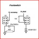
From point B to the switch, connect the switch and you have 'whatever the correct term is' for the stuff coming from point B of the cathode now adding the 400 ohm resistor and 25uF cap before it goes to ground. Maybe you are seeing a direct line to ground due to the drawing
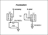
Please assume I know how to hook it up, the amp does work, and quite well. The drawing is supposed to represent the cap and resistor wired in parallel to ground from the switch. I see the line from the switch to the box may look like it's not connected that way, but I would not have a very nice sounding amp if it were like you are understanding it. The picture is a better representation because that is what I am using.
It seems like too much is being made out from my drawing.
The only issue is: can I switch in an additional resistor on any preamp cathode w/o popping noise? (not including the FET info) And for that matter, switching in a bypass cap w/o popping noise also. The cap issue has been resolved as far as I am concerned-the time constant wrt resistor.
With that said: Imagine a 12ax7 cathode w/ a 1.5K resistor to ground. I want to add another resistor, in parallel, to change the value of the resistance on the cathode. Any switch, anywhere. Can that be done w/o popping noise?
With that said: Imagine a 12ax7 cathode w/ a 1.5K resistor to ground. I want to add another resistor, in parallel, to change the value of the resistance on the cathode. Any switch, anywhere. Can that be done w/o popping noise?
I don't think it can be done with just a switch. The reason...
Placing a different value cathode resistor in circuit by means of a switch presents an instantaneous change to the DC and AC characteristics of the circuit. That results in a pop/click/noise.
The other extreme to that is imagining the cathode resistor as a variable resistor such that you can alter it slowly. That would not cause a click or pop.
Using a FET (and remember I said it's an idea and you would have to try it) would allow for a more gradual change in the DC/AC conditions that would hopefully be much less audible, maybe not at all.
Hey Mooly, thanks. I was afraid after all the discussion that it wasn't going to work. But I will keep the FET info you posted for future experimenting.
I did try a pot on the cathode for a variable resistor but when you turn the wiper it made a loud scratching noise. That's why I went w/ rotary switch. If I could eliminate the scratch noise the same idea could be modified into a volume foot pedal. Not that it's really necessary, just possible.
Thank you and everyone for all your help...
Daniel
dscottg,
As I said before, if you have only resistors in the circuit between the cathode and ground, and you throw a switch and then have only resistors in the circuit between cathode and ground, a small capacitor between cathode and ground that is ALWAYS in the circuit may get rid of the pop. It depends on the size of the capacitor.
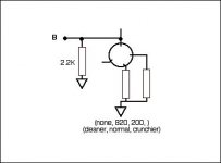
It needs to be small enough that it has a higher impedance at 1kHz than your highest resistance combination, which in this case appears to be 2.2k on the B tube.
And it needs to be big enough to keep from charging near instantly THROUGH the resistors.
Try different values and see what happens. A small capacitor will have little effect on the audio, whether you later switch in a big capacitor or not, whether you have a capacitor in the circuit and switch it out.
Have your tried this solution yet?
As for the pop you get when you switch a 500uF cap into the circuit (or out of the circuit), have you tried using a 2.7 Ohm resistor in series with the capacitor? (NOT 2.7K! Use 2.7 Ohms! Red-Purple-Black-Gold. I see that you
As I said before, if you have only resistors in the circuit between the cathode and ground, and you throw a switch and then have only resistors in the circuit between cathode and ground, a small capacitor between cathode and ground that is ALWAYS in the circuit may get rid of the pop. It depends on the size of the capacitor.
It needs to be small enough that it has a higher impedance at 1kHz than your highest resistance combination, which in this case appears to be 2.2k on the B tube.
And it needs to be big enough to keep from charging near instantly THROUGH the resistors.
Try different values and see what happens. A small capacitor will have little effect on the audio, whether you later switch in a big capacitor or not, whether you have a capacitor in the circuit and switch it out.
Have your tried this solution yet?
As for the pop you get when you switch a 500uF cap into the circuit (or out of the circuit), have you tried using a 2.7 Ohm resistor in series with the capacitor? (NOT 2.7K! Use 2.7 Ohms! Red-Purple-Black-Gold. I see that you
I wrote nearly a doctoral dissertation over the last two hours, editing carefully for accuracy and to clarify the electronic behavior of resistors and capacitors in parallel I think it would help you to brush up on, and gave you the formula for calculating the impedance of a capacitor at a given frequency, the capacitance for getting a particular resistance at a given frequency, how to easily shift those values up and down as you change the frequency, and for calculating the resistance of two impedances in parallel . . .
and got an infuriating message that the system was down for maintenance and would save my post automatically . . .
only it didn't. It saved only about a tenth of it.
and I am not about to write all of that over again.
Sorry. I wish you could have read what I wrote.
But I'm gone.
Let us hope that some moderator will replace all that evaporated knowledge at his leisure.
Well, if you only need exactly those voltages, maybe.
Have you verified this?
Every red one?
Every yellow one?
. . .
Most, yes, and yes, I have done a lot of experimental verification. Catalogs are very helpful in choosing different Vf.
2.2k in one position.
200 ohms in parallel with it makes maybe 180?
For maybe 0.2 volts bias?
Which diode now?
Schottky.
Hi Tube,
Yes, I tried the cap to ground, used a .001, the largest you recommended, and no result.
And, on the 500uF cap, no, but I'll try it. I have a 3.3 ohm, close enough.
I have a feeling that the placement of the 500uF cap wrt the switch may be an issue. My switch connects the cathode to the capacitor, 'downstream from the switch'. It could be placed to connect the ground side of the cap to the switch and then to ground. 'Upstream from the switch'
A guitarist who checked it out for me never mentioned the popping. I haven't got a word back if he remembers it, but I'm guessing it must not have been that loud to him.
I've packed it up and am sending it out to my nephew, so it is done. If I can figure it out someday, I'll send him a new footswitch. I'll work on this w/ another amp now.
Thanks everyone for all the input, time and energy helping me. Even though I didn't resolve the problem, I still learned quite a bit from all the responses.
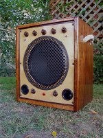
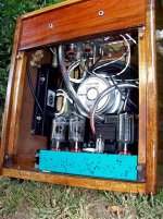
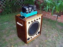
Here is picture of the amp, in case you're interested...
Yes, I tried the cap to ground, used a .001, the largest you recommended, and no result.
And, on the 500uF cap, no, but I'll try it. I have a 3.3 ohm, close enough.
I have a feeling that the placement of the 500uF cap wrt the switch may be an issue. My switch connects the cathode to the capacitor, 'downstream from the switch'. It could be placed to connect the ground side of the cap to the switch and then to ground. 'Upstream from the switch'
A guitarist who checked it out for me never mentioned the popping. I haven't got a word back if he remembers it, but I'm guessing it must not have been that loud to him.
I've packed it up and am sending it out to my nephew, so it is done. If I can figure it out someday, I'll send him a new footswitch. I'll work on this w/ another amp now.
Thanks everyone for all the input, time and energy helping me. Even though I didn't resolve the problem, I still learned quite a bit from all the responses.
Here is picture of the amp, in case you're interested...
Attachments
")
Somehow I did not see all the posts, Tubekit, thanks for your effort, it's appreciated. Just so you know, I have a degree in physics and know the science and math of all the components, I just don't fully know how it pertains to tube amps and I am teaching myself w/ books and forums, etc... I looked up capacitive reactance and the formula and understand how it acts as a resistor.
Hope you're not doing another dissertation...
Daniel
Hope you're not doing another dissertation...
Daniel
Even so, diodes do not produce truly fixed voltages. They are slippery little critters with Vf values that slide all over the place depending on the impedance of the circuit that you put them in, and I know this from my own "experimental verification." That in itself is enough to make me wary of using them to regulate a vacuum tube's cathode bias, since the impedance of the tube is going to be changing constantly. Granted, a resistor will change voltage as the current through it changes, and a diode less so, but the diode is not a fixed regulator, after all. And I've heard the thermal noise introduced into a tube by a semiconductor in the cathode circuit, so I'm beyond reach of the "theremal noise is not an issue" fiction, to mention another potential problem. Again, the cathode bypass cap can filter out most such noise--when it is there. But when it isn't? Or doesn't?"Most, yes, and yes, I have done a lot of experimental verification. Catalogs are very helpful in choosing different Vf."
The spec sheets usually specify a minimum, and a maximum likely voltage at two or more current levels, and may specify a typical value--but it's not guaranteed. The voltage depends on the forward current. Speaking of which, sometimes they shut completely off if you try to pass too little current through them.
A tube that wants to operate in a very high gain stage with a huge plate resistor may draw only a fraction of a milliamp. The diode won't pass anything at all. Voltage across diode: effectively plate supply, for just a millisecond--which possibly means burned out diode, after which the voltage is zero.
Try to find a diode in your catalog that can be forward biased in a 300-volt circuit to pass 0.375 mA while producing a known Vf.
Diodes are just too unpredictable for everyday use in this way. In some circuits, perhaps. But it's not a foolproof solution to the need for a specific bias voltage in just any given situation.
- Status
- This old topic is closed. If you want to reopen this topic, contact a moderator using the "Report Post" button.
- Home
- Live Sound
- Instruments and Amps
- rotary switch for different cathode resistors