Hope this makes sense.
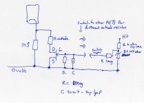
The FET switches the cathode resistor in or out of circuit.
The gate of the FET is connected via the switch to a fixed "bias" supply of around 8 volts. This voltage is determined by the zener and can be up to the maximum Vgs (voltage gate to source) for the FET chosen. The voltage feeds via a 1 meg into the gate of the FET. The cap C causes the voltage to rise exponentionally causing the FET to come into conduction more slowly. I think that will stop the noises you hear from an abrupt switching action. You can alter the value of the cap to get a slower turn on. The resistor R which I put at 10 meg discharges the cap and ties the gate of the FET to ground to ensure it is off when not selected. The 1 meg resistor to the switch wiper serves as many FET's as you want to run.
You would have to experiment with the values of R and C.
The "on resistance" of the FET is in the milliohm region and the FET must be an N channel device. Something like the IRF2907 although check that the voltage on the cathode does not exceed the devices 75 volt rating. Plenty of high voltage types if needed.
http://www.datasheetcatalog.org/datasheet2/1/02e3z9gtd7pa3su47xt0a58si0fy.pdf
Attachments
Thanks Mooly, (I didn't see the 'L' in your name before, sorry bout that)
If I understand correctly:
The FET is the DGS piece, and the H+ can be a 9v battery or plug, w/ a correct resistor to achieve 1mA. That's connected to the anode of the diode, and the 1M resistor going to the switch. The other side of the switch is going to the resistor, capacitor and to the G on the FET/ while the resistor/cap are connected to ground. D gets connected to the resistor I am switching to and S goes to ground. The other FET switches would be for the rotary switch with the other resistor values to change to. Yes??
The only question about the schematic is the C to suit. Is that a cap I am also switching into the circuit? or Is that for the FET's operation?
Thank you...
The only part I don't understand is how it works.
Oops! I missed another detail.
To kill the pop when you change the resistor, you need to put the little cap all the way between the cathode and ground, not across the switch.
That way, the cap charges to whatever voltage is on the cathode with whatever combination of resistors you have. It is far too small to effect the low frequency rolloff or gain of the stage at audio frequencies if you choose it well. (Keep it small.)
When you switch another resistor into the circuit, the cap still has the "old" voltage across it, so the sudden appearance of the new resistance does not suddenly change the voltage. The little cap has to discharge (or charge) through the resistor(s) that are now in the circuit, and since its reactance (effective resistance) is very high, this takes a finite amount of time, preventing a pop. The only exception to this would be if you have one position in which there are NO resistors between the cathode and ground. In that case the contact resistance of the switch would not be enough to slow the discharge of a little cap unless it isn't a little cap.
But as long as you have SOME resistance in the cathode circuit in every possible switch position, then the small cap solution is your simplest, cheapest, and cleanest solution.
It should have no effect on the sound of your amp.
Unless I am mistaken, even an FET will need a smoothing cap somewhere in the circuit to get rid of the pop, unless its slew rate is naturally very slow. But in that case, I would expect it to be an obsolete FET, or at least pretty useless in any modern high-tech deivice. But I've not gotten very much into FETs so I'm not really sure about this.
However, an FET can introduce thermal noise into your circuit, especially if you put it into the signal chain at the first stage.
The cap is non-intrusive, requires no bias voltage, no care and feeding, and injects no noise.
Keep it simple.
At 20kHz, a 100pf cap has an impedance of about 79K.
At any lower frequency, its impedance goes up to bigger than 79K. So 79K is its minimum impedance for any audio frequency.
Since 79K is more than 50 times the resistance of a 1.5K cathode resistor, it is safe to say that no audio is going to "leak" around such a cathode resistor via a 100pF cap. In other words, a 100pF cap is not going to increase the gain of the stage for any audio frequencies.
My guess would be that, if your smallest cathode resistor is 1.5K, you could safely go as high as .001uF with your pop-filter cap (possibly even higher) without affecting the gain of any audio frequency, and therefore without affecting the frequency response or sound of the amp.
So if you start with a small value like 100pF and increase only as needed until the pop is gone, you should be in good shape.
This hypothesis is not tested, however. That's your mission, if you should decide to accept it.
But it can't hurt to find out.
Thanks Mooly, (I didn't see the 'L' in your name before, sorry bout that)
If I understand correctly:
The FET is the DGS piece, and the H+ can be a 9v battery or plug, w/ a correct resistor to achieve 1mA. That's connected to the anode of the diode, and the 1M resistor going to the switch. The other side of the switch is going to the resistor, capacitor and to the G on the FET/ while the resistor/cap are connected to ground. D gets connected to the resistor I am switching to and S goes to ground. The other FET switches would be for the rotary switch with the other resistor values to change to. Yes??
The only question about the schematic is the C to suit. Is that a cap I am also switching into the circuit? or Is that for the FET's operation?
Thank you...
The only part I don't understand is how it works.
Most get it as Molly
")
If you are interested in the idea then I would recommend just trying a "lashup" with one FET.
The FET is the DGS device.
It works like this... the FET is normally non conducting between D (Drain) and S (Source) as long as the voltage between gate (G) and source is below around 4 volts.
You could use a 9 volt battery to provide the turn on voltage. If so then the zener and resistor to H are not needed. 9 volts is fine on its own. You still need the 1 meg to the FET.
I put H as your main HT line and R to be calculated to allow around 1 ma to flow through the zener so that it would all run off the amp PSU. So if the HT were 300 volts then R would be 300 less 8.2volts (zener volts) divided by 1e-3 giving approx 292K. So a 270 or 330k would be fine. That would give a stable voltage across the zener. The 1 milliamp is an arbitrary figure and very non critical.
That is all the resistor and zener do. The zener gives a stable voltage across it equal to the zener voltage chosen.
The FET works as follows.
With its gate and source tied together with a high value resistor the FET is always OFF. So the cathode resistor is effectively out of circuit.
If the voltage on the gate is increased, then at around 4 volts or so the FET will begin to conduct and by the time the voltage reaches around 6 volts the FET will be fully conducting placing the cathode resistor in circuit.
So my idea is that if we arrange for the gate voltage to rise slowly then that means the FET doesn't suddenly change from non conducting to conducting but passes thorough a zone where conduction occurs slowly. As the gate of the FET draws no current at DC we can place a simple RC network there to generate a slowly rising voltage.
The only part of the FET that is "in the audio" path is the drain-source path and that is either fully OFF or fully ON. The network on the gate plays no part in the audio route. Just think of the FET as a wire link (apart from when it's being switched) in that its either there or not.
So I would suggest trying the idea first to see if the slow switching does achieve a silent change of cathode resistor.
The value of the cap would have to be determined experimentally.
The FET needs the permanent high value resistor between gate and source to ensure that the gate isn't "floating". I put 10 meg for that. The resistor feeding the gate (from the 9 volt battery or 8.2 volt zener) I put at 1 meg.
So the cap is chosen to give as much "slowing down" of the gate voltage as needed. It can be 1uf or 10 uf or 100 uf.
When you close the switch the voltage across C can only rise as quickly as the 1 meg can charge it. So what happens is that the voltage ramps up slowly causing the FET to enter conduction slowly. Higher value cap and the ramp is slower taking longer to reach the 9 volts supplying it.
Try it with one FET and battery etc.
Keep it simple.
The FET is a lot of trouble to go to simply to get rid of the pop. The only reason I can see to use an FET is if it allows you to get the caps out of your footswitch body and back up into the amp, since the caps carry audio, whereas the DC bias resistors do not carry audio unless they are not bypassed by a sizeable cap.
If you just want to get rid of the pop that accompanies switching resistors . . .
Try the little cap first. It's simple enough. Won't take you two minutes to see if it works.
Just put a 100pF cap between the cathode and ground. If it works, you're finished.
If not, make it bigger. Again up to .001 uF should have no effect on the audio--only on the pop.
If it doesn't kill the pop before it's big enough to hear (but it allmost certainly will), then you can go to all the trouble of using an FET.
And the "only part of the FET that is in the audio path" WILL introduce thermal noise into your circuits, particularly high gain first stage circuits where that noise could potentially be a meaningful percentage of the signal voltage. A saturated FET is NOT a wire, it is a semiconductor resistor of very low resistance. (Read: thermal noise.)
It's also more expense.
Thanks much everyone....
I have some experimenting to do now. I will try Tubekit's idea first, as it is the simplest. But, one question about that is, when I have a bypass cap in place, say a 47uF and then change resistors, there is a pop. So, why would a small cap eliminate this?
And I don't see much thermal noise as a problem because I am dealing with the cathode voltage that is around 2-4v DC. Since it is not in the signal path that I am amplifying it shouldn't be a problem. I don't know for sure though...
I'll let you all know a little later how it's working out....
Thank you all again....
No luck at all...
Well, I am sorry to report that the pop is still there. Even when switching in only a capacitor and having 1M resistor across the switch, it still pops. Now I am confused.
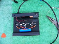
Here is a picture of what I have now. For other reasons I changed to this switch. You can see the 1M across the switch with the 500uF/30v cap. It still makes a pop when switching it in the circuit to ground. Once it's charged it does not pop when turned off.
On the left I didn't put a resistor across because of the one that is being added to the circuit.
Have I done something wrong, or am I misunderstanding something? Especially wrt the 500uF capacitor.
Any thoughts??
Well, I am sorry to report that the pop is still there. Even when switching in only a capacitor and having 1M resistor across the switch, it still pops. Now I am confused.
Here is a picture of what I have now. For other reasons I changed to this switch. You can see the 1M across the switch with the 500uF/30v cap. It still makes a pop when switching it in the circuit to ground. Once it's charged it does not pop when turned off.
On the left I didn't put a resistor across because of the one that is being added to the circuit.
Have I done something wrong, or am I misunderstanding something? Especially wrt the 500uF capacitor.
Any thoughts??
Attachments
The time constant for a 500uF cap and a 1 meg resistor is several minutes, so it's going to pop unless you leave it for a while before you switch. And even then, a 500uF cap is likely to have more leakage current than a 1 meg resistor will give, and it may never really charge up. Try a 10 to 47 uF cap, and a 47k to 100k resistor across the switch.
Also, (I don't recall if you already know this or if it was mentioned in the thread) be sure the polarity is correct on the electrolytics. The - connection should go to ground, and the + should go to the switch which connects it to the cathode.
Also, (I don't recall if you already know this or if it was mentioned in the thread) be sure the polarity is correct on the electrolytics. The - connection should go to ground, and the + should go to the switch which connects it to the cathode.
What's the frequency, Kenneth?
Yes, Mooly, if every position of the switches includes a capacitor to ground from the cathode, then the small cap solution doesn't add anything. But if there were a cap from cathode to ground in every possible combination of switch positions, then I would not expect a pop when changing only resistors unless one of those options was to connect the cathode directly to ground. And I thought I heard reference to a pop occurring when only the resistor was being changed, which suggests the possibility that there is no cap in the circuit when that pop occurs. It seems we have more than one kind of pop here.
Perhaps the source of the problem is partly the switch. If the switch is a break-before-make with a long time between makes, it is always possible that the time between losing contact with one resistor and making contact with another is long enough for the capacitor(s) in the circuit at the time to change voltage before the next resistor in the circuit reverses that. That would suggest protecting each and every resistor and capacitor separately from pops. An expensive proposition with FETs, but not with little caps and resistors.
And yes, the time constant of 1 Meg with 500uF is very very long. Switching back and forth before waiting that long, long time is going to create a pop even if the circuit is wired correctly. But if the OP wants the 500uF cap, the cure is to use a smaller resistor. Again, the point I made earlier about the ratio of the resistance of a fix with the resistance of the cathode resistors is important. Any passive anti-pop solution to the SWITCHED CATHODE RESISTOR-caused pop requires an impedance that is greater than the highest cathode resistor by a factor of better than five-to-one or more. With cathode resistors in the 1 to 2 kilohm range, a Megohm anti-pop filter is overkill by a factor of about 100:1. Considering the various values of cathode resistor that might be in the circuit at various times, perhaps a 47k resistor would be enough. Certainly a 100k resistor would be enough.
But 100K x 500uF is still 50 seconds. And that's just the time it takes to charge or discharge 63%. For the whole 100% to kill ALL pop, one needs more like 5 times T, which would be 250 seconds, or about four minutes. Even 10uF and 100K is going to take a full second to dis/charge and 47K is only going to cut that in half. Times 5 gives us two and a half seconds of needed stability before the pop filter can be guaranteed to work. And if the phatness the OP is looking for needs 500uF, then 10uF isn't going to get anywhere near it.
With a 1K cathode resistor the difference between a 10uF cathode bypass and a 22uF bypass is easily audible, and 100uF takes bass response much lower than either making still an audible change for a cathode resistor smaller than those being used here. I can easily see why the OP wants 500uF.
Perhaps the FET is the solution after all. (But it's so MESSY!) In that circuit, the shock-absorber capacitor is not in the cathode circuit and its time constant is independent of the cathode circuit impedance.
On the other hand, if one changes one's approach to a solution, the resistance of the 500uF cap anti-pop resistor is not dependent on the cathode circuit impedance, but only on the impedance of the 500uF cap. That impedance is around 14.6Ohms at 20 Hz. So a series resistor that keeps it charged when "not" in the circuit only needs to be about 100 times as big as that to make the 500uF "go away completely" at 20Hz. This is only about 1500 ohms.
That resistance is going to give a time constant of only 750 milliseconds. Now we're in the world of practical solutions! And a 500uF cap in series with a 1500-Ohm resistor is not going to bypass anything that a 1.5K resistor doesn't, nor is it going to affect the frequency response at 2,000Hz any more than a .05uF cap would all by itself. In other words, its effect will get lost in the effects of the other caps in the circuit, just as Mooly mentioned above.
But there may be an even better way. Just put a 2.7 ohm resistor in series with the cap as though it were part of the cap and switch it in and out of the circuit WITH the cap. That much resistance will slow the inrush of current when switching it into the circuit without affecting the total capacitive reactance or frequency response noticeably.
The problem of getting pop when changing only RESISTORS is a different problem and requires a different solution.
Something tells me that these problems may be yet unsolved because of the placement of the anti-pop component(s). You said "across" the switch. I couldn't fully understand what the switches were doing in your schematic, because they are not drawn as a conventional circuit diagram draws a switch: the poles and throws being circles with the movable switch contact (vector arrow) being shown as well. The function of each switch is not clear to me just from their placement and your description of the effects you're seeking. If these are drawn as slide switches are often drawn, the sliding contacts are missing from the drawing, so I can only guess at their function. It may be a good guess, but I can't have complete confidence in it.
There are also more components connected to the switches than I had been expecting, and in unexpected ways. One example: you have a resistor labeled 0 Ohms. But it appears to be in parallel with a fixed, unswitched resistor. If that is the case, then switching the 0-Ohm resistor into the circuit shorts out the other one, rendering it useless. So I suspect that what you mean is Infinite ohms, not 0 ohms. With the rotary switch in that position, there is NO resistor connected by the rotary switch, correct? Other resistors appear to be confusingly labeled as well. Are you using a "K" where you meant to use an "R" or vice versa?
And the 1.5 caps. Is this 1.5 uF, nF or pF? And are these always in the circuit or sometimes not in the circuit?
This is what I mean when I say that it may all depend on what you mean by "ACROSS" the switch.
Now that I've also looked at the picture closely, I'm just about as confused as ever.
It appears that you may have the 1 Meg resistor connected from one throw of the switch to the other throw on that pole, which would do you no good at all, suggesting that it is my interpretation of the picture rather than the way the resistor is actually connected. It impossible to tell from the angle of view. We're really just chasing our tails here, not knowing what the problem IS, so we can't yet know how to fix it.
Could you draw just ONE complete cathode circuit with all of its switches please? (The one with the 1 Megohm resistor.) And please draw the switches in standard electronic notation (with arrows extending from and to circles representing poles and throws), rather than as just a group of connections to a rectangle. And please label every resistor and capacitor with complete notation of their exact values.
That will make the whole thing much easier to understand.
Anyway, here's my bottom line suggestion:
Generally speaking, put a small cap (reactance at all audio frequencies much higher than the resistor it shunts) in parallel with every cathode resistor. Put a small resistor (resistance much smaller than the reactance at relevant frequencies of the capacitor it shields) in series with every cap.
Then switch these combinations into and out of the circuit any way you like without worrying about what to connect "across" the switch.
Please excuse the long reply, but you have come up with a very complex problem that is still only indistinctly visible from here and its solution may also need to be complex and repeated multiple times. Doing that with FETs could get expensive.
Knowing component values is important because the frequencies at which a component or a pop fix is effective in this case changes with them.
Corrections
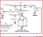
I redid the schematic and hope it is correct. There were a couple of errors. And this has the new footswitch.
Okay, please understand I am not very experienced and only draw what I understand. I have two different switches. A rotary- that switches different resistors on the cathode. The 'zero' ohm one is meant to be no resistor added, using only the 2.2K directly on the cathode. Then I have and 820 ohm and a 200 ohm resistor to switch to.
In addition to that switch I have the foot switches; a 25uF/25v cap in parallel w/ a 400 ohm resistor on one and a 500uF cap on the other. (I mentioned I changed foot switch in my last post so the schematic foot switches (four DPDT's) are not being used. The picture is to replace a drawing I did not do.
The picture shows a wire from one cathode going to the 'left' switch-center position. Connect the switch and it adds the cap and resistor into the network in addition to the 2.2K and the one on the three position rotary switch. (Yes, this is probably overkill, but I had the switch before I realized that and can't change the position or cover up the hole.) I'm just including it and it really only works when the footswitch is not used.
The other wire goes to the right switch and adds a 500uF capacitor. But since the dual triode is wired in parallel it only 'sees' 250uF. That is what the Marshall uses and why I chose it. That has a 1M resistor 'across' the switch. At least that is what I understand as 'across the switch'. It is connected between the center lug (input) and an end lug (output). Yes?? It connects the capacitor to the wire via this resistor. Do I not have it placed correctly?
So, do not look at the footswitch schematic on the other drawing. I changed it because there was no difference I could tell between switching from a 1.5uF cap to a 400uF cap. I thought there would be a bright/dark difference but there was not, so I decided to simplify and make 2 switches only and that is the one in the picture.
Everything on the schematic is in ohms and uF, it's the same convention I've seen on other schematics.
Sorry about missing some details that may have confused you. I am new at this...
Thanks again, Daniel
Attachments
Last edited:
In addition, I can see the time constant issue w/ the large cap. I can add smaller values, probably down to 10K ohms w/o affecting the total resistance on that cathode. Is that what helps the time for charging?
And, the popping noise is there with both foot switches. If the rotary switch pops when changed it's not that crucial because it is not on the 'fly' while playing live like the footswitches are. That is why I am trying to make it as quiet as possible.
I hope I have cleared everything, please ask questions if I'm not being clear or correct.
Thank you...
I'll come back to it...
Just as drawn and your switch V2 shows as connecting point B directly to ground when the switch is operated... typo ?
If switching a cap in parallel with a resistor (25uf and 400 ohm) as one example then then the cap when switched out of circuit is always initially discharged and so when switched into circuit it will give a pop or click as it instantly alters the DC bias of the valve only returning to normal as the cap charges.
- Status
- This old topic is closed. If you want to reopen this topic, contact a moderator using the "Report Post" button.
- Home
- Live Sound
- Instruments and Amps
- rotary switch for different cathode resistors