Hello everyone.
I recieved this amp in for repair. Someone had changed the transformer, the driver transistors (A06 & A56), and in the process of trying to change the output fets destroyed the MESHA board.
I removed the MESHA board and applied Kapton M/T and replaced all the output fets, as they were shorted.
The amp powers up fine and idles. There is no DC on the output terminals at an idle but driving a 100Hz sine wave into the amp at full volume there is 2 vdc on the + output terminal.
The amp produces good bass if you will but there is a buzzing or frequency noise through the speaker. I can also hear a slight buzzing noise inside the amp, almost sounds like it is coming from the MIC4420CT driver but not sure.
All of the op-amps have +/- voltage on the supply pins.
The amp has a rail voltage of 88 vdc on the r/b wires.
The LM339D reads as follows:
pin 1: 4.51 vdc
pin 2: 4.51 vdc
pin 3: 17.45 vdc
pin 4: 0.314 vdc
pin 5: 2.347 vdc
pin 6: 4.34 vdc
pin 7: 5.01 vdc
pin 8: 0.733 vdc
pin 9: 0.733 vdc
pin10: 5.01 vdc
pin11: 8.21 vdc
pin12: 0.001 vdc
pin13: 4.51 vdc
pin14: -0.001 vdc
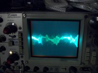
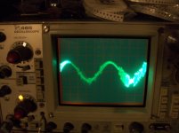
I have included 2 pics of the output on the scope, 1st pic is at low volume and 2nd pic is at 1/2 volume.
Scope settings are 20 vol/div 2 ms
Can someone push me in the right direction of what I should test first?
The output does not seem distorted but like there is interference with it if that makes sense.
I recieved this amp in for repair. Someone had changed the transformer, the driver transistors (A06 & A56), and in the process of trying to change the output fets destroyed the MESHA board.
I removed the MESHA board and applied Kapton M/T and replaced all the output fets, as they were shorted.
The amp powers up fine and idles. There is no DC on the output terminals at an idle but driving a 100Hz sine wave into the amp at full volume there is 2 vdc on the + output terminal.
The amp produces good bass if you will but there is a buzzing or frequency noise through the speaker. I can also hear a slight buzzing noise inside the amp, almost sounds like it is coming from the MIC4420CT driver but not sure.
All of the op-amps have +/- voltage on the supply pins.
The amp has a rail voltage of 88 vdc on the r/b wires.
The LM339D reads as follows:
pin 1: 4.51 vdc
pin 2: 4.51 vdc
pin 3: 17.45 vdc
pin 4: 0.314 vdc
pin 5: 2.347 vdc
pin 6: 4.34 vdc
pin 7: 5.01 vdc
pin 8: 0.733 vdc
pin 9: 0.733 vdc
pin10: 5.01 vdc
pin11: 8.21 vdc
pin12: 0.001 vdc
pin13: 4.51 vdc
pin14: -0.001 vdc
I have included 2 pics of the output on the scope, 1st pic is at low volume and 2nd pic is at 1/2 volume.
Scope settings are 20 vol/div 2 ms
Can someone push me in the right direction of what I should test first?
The output does not seem distorted but like there is interference with it if that makes sense.
Attachments
The DC isn't showing up at the IC.
Try connecting the pot to it to see if everything is switching properly. Remember to pass through the transition point quickly. You can try it with the resistors in the circuit. I wanted to try it that way but haven't had a chance.
Check for DC on the speaker terminals when it's in both states (clock/counter-clockwise on the pot). It shouldn't have any DC in either position.
It doesn't matter as long you select one from each group. You can use the ones on each end if you want. Check the gate drive and also make sure they're switching the drains properly.
I checked one out of every group of three. Q110, Q104, Q107, Q101
When the pot is turned they are all switching from +/- 9.75 vdc
When you say check the gate drive to make sure they are switching the drains properly do you mean red probe on gate and black probe on drain and turn pot to see if drains are switching on and off or from + to -?
Not quite sure how to check that?
Red on gate and black on source would be how you'd check the gates. To check the drain switching, you'd place the black probe in the amp or speaker ground and the red probe on the drain. You should get full rail on the drains. The polarity should reverse when the gates switch.
You won't drive signal into the amp during these tests.
Yes, check for DC in both states.
I just checked for DC with no signal driven to the amp in both states.
There is + 109.5 vdc on the terminal in one state and - 109.5 vdc on the terminal in the other state.
Why is this voltage not present when the amp is having a signal driven into it.
The measurments I gave you from U17 LM6171 were with a signal being driven at full volume and it had 2 vdc on the + speaker terminal.
Should I re measure the U17 without a signal to see if the DC is at the IC now?
I checked drain switching on the same fets as I checked the other switching on. Q110, Q104, Q107, and Q101
In one state of the pot they are all at 0.000 vdc and upon rotating the pot the drains recieve 107.5 vdc rail voltage +/- depending on if they are IRF6215 or IRF3415.
I am assuming this all looks ok as far as the switching?
In one state of the pot they are all at 0.000 vdc and upon rotating the pot the drains recieve 107.5 vdc rail voltage +/- depending on if they are IRF6215 or IRF3415.
I am assuming this all looks ok as far as the switching?
- Status
- This old topic is closed. If you want to reopen this topic, contact a moderator using the "Report Post" button.
- Home
- General Interest
- Car Audio
- Rockford Fosgate BD10001