Thank you guys, Chris, Dave, for response!
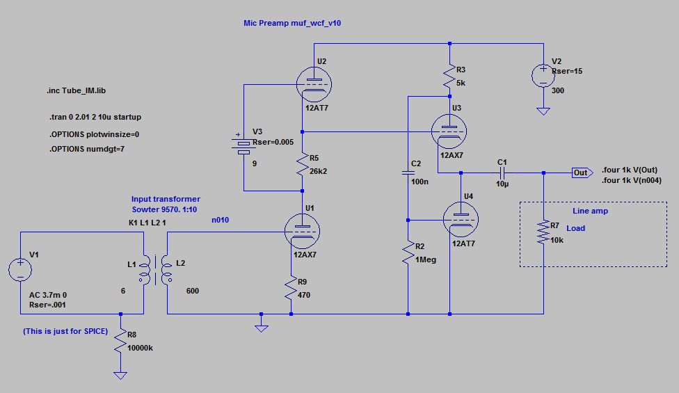
It is invisible on the schematics, but mic already includes its own transformer 1:37 that produces ~3.7mv from 0.1mv of ribbon's EMF. This transformer creates 200R impedance.
The MuF+WCF schematic amplifies 3.7mV to 3.1V on output.
Is it not enough for some another amp line input?
I read standard line input should take 1.5-2.5V. But I am not sure, is it a whole swing from -0.75 to +0.75 or it is -1.5 to +1.5?
3.1V will work for your ADC as 0db ref on that chip is 3.3V
thanks!
Is 3.3V from minus bottom to plus top or from middle 0 to either side?
what chip is it? (may be I'll need other details of it)
This has all been a very juicy read! That was going to be my next question. 9v battery choice? What about that input transformer? How affordable high end can we go? Edcor? Sowter?
Ive been looking around for documentation on the White Cathode Follower, and it seems like a popular hit. But why? I found alot of formulas but no overview on its function.
Ive been looking around for documentation on the White Cathode Follower, and it seems like a popular hit. But why? I found alot of formulas but no overview on its function.
Hi woodrough.
Batteries are different. Though they specify 9V, the actual voltage may differ and depends on a type, i.e. rechargeable with not rechargeable. All I found that Li rechargeables have 8.4V, and not rechargeable have 9.6V.
I am not sure, I think it should be measured. I am going to use Energizer because they post at least some datasheet. Just in case I've calculated R5 values for different voltages and may be will make some internal switch.
Regarding transformer I've contacted Lundahl, just couple of hours ago.
Why Lundahl, because I use their 1:37 in my mic so they may know better.
WCF has high input impedance and gives lowest output resistance/impedance.
So we do not need to use a step down output transformer if we need to lower impedance of MuF(~1.5k).
But it depends on your line amp. May be it has high input impedance like 47k and 1-st stage MuF can be plugged into it without WCF.
In my case line input has 3.3k impedance, and I've decided not to take a risk.
Also it utilizes same tubes (if it is mono).
Last edited:
Hey mm7,
All interesting food for thought. Is it goofy as hell to put some Li batteries (a 9v and a button or two) in series? Or is this defeating the point by littering the signal path with junk. I guess the only way to know is to try it out
Im curious to find out what Lundahl has to say. Im sure my wallet is not.
I guess its nice to be safer than sorry. Is it possible to be too safe? My macbook sound card is impedance is < 20 kΩ. What are you recording with? I also like the same tube mono feature. Thats sweet
I looked on voltage-time charts, and they show initial voltage about 9.6V. But it drops to ~8.4V after some minutes of working with some load like 900Ohm and then it lasts horizontal for some hours.
1604LC* | Datasheet Archive
May be aging it to 8.4V and then using will work? Also I read that voltage may increase up to 10V if circuit is open. And in our case it is open.
I am not sure. It should be experimented.
If use buttons, I'd use 3 buttons of 3V same type serialized in a container.
Per Lundahl has kindly suggested:
I am recording to E-MU 0404 PCI. It has 10K static resistance (measured), and 3.3K impedance (documented).
1604LC* | Datasheet Archive
May be aging it to 8.4V and then using will work? Also I read that voltage may increase up to 10V if circuit is open. And in our case it is open.
I am not sure. It should be experimented.
If use buttons, I'd use 3 buttons of 3V same type serialized in a container.
Per Lundahl has kindly suggested:
it is $76 at K & K Audio - Lundahl Transformers, audio DIY kits and morefor a 1:10 mic input I suggest the LL1935 http://lundahl.se/pdf/1935.pdf
It is described as a 10:1 DI transformer, but works very nicely as a 1:10
mic input transfomer.
- Per Lundahl
I am recording to E-MU 0404 PCI. It has 10K static resistance (measured), and 3.3K impedance (documented).
Last edited:
Sorry my English style.
I have a question, Marik. You say your transformer 1:36 has a primary DCR 0.002 Ohms. Given that the connecting wires of a transformer having about 10 centimeters each, add the DCR of the coil itself, which at least for a material such as amorphous tape wound, for about 4.5 to 5 mH need at least 6 or 7 turns. For the dimensions of your toroid you need at least 20 cmts of wire. In total would be 20 +10 +10 = 40 centimeters. One meter of enamelled copper wire 1.4 mm in diameter is 0.0107 ohms, 40 cmts will be approximately 0.00428. A wire gauge that is very difficult to handle both for winding wires to wiring within a microphone. Connecting wire only be 0.002. If you parallel several wire coils finest would have a problem with space inside the toroid. I am a fan of Marik, but I find this fact very critical.
I have a question, Marik. You say your transformer 1:36 has a primary DCR 0.002 Ohms. Given that the connecting wires of a transformer having about 10 centimeters each, add the DCR of the coil itself, which at least for a material such as amorphous tape wound, for about 4.5 to 5 mH need at least 6 or 7 turns. For the dimensions of your toroid you need at least 20 cmts of wire. In total would be 20 +10 +10 = 40 centimeters. One meter of enamelled copper wire 1.4 mm in diameter is 0.0107 ohms, 40 cmts will be approximately 0.00428. A wire gauge that is very difficult to handle both for winding wires to wiring within a microphone. Connecting wire only be 0.002. If you parallel several wire coils finest would have a problem with space inside the toroid. I am a fan of Marik, but I find this fact very critical.
what kind of PSU will be good here? Regulated I guess?
Does it need regulated DC heater supply?
How to elevate heaters of upper tubes?
My concern here, because upper tubes are in same envelopes with the lower ones, if I elevate upper heater to 150VDC, so it is 50VDC above its cathode, the lower tube heater will be elevated 148VDC above cathode, isn't it too much?
Sorry my English style.
I have a question, Marik. You say your transformer 1:36 has a primary DCR 0.002 Ohms. Given that the connecting wires of a transformer having about 10 centimeters each, add the DCR of the coil itself, which at least for a material such as amorphous tape wound, for about 4.5 to 5 mH need at least 6 or 7 turns. For the dimensions of your toroid you need at least 20 cmts of wire. In total would be 20 +10 +10 = 40 centimeters. One meter of enamelled copper wire 1.4 mm in diameter is 0.0107 ohms, 40 cmts will be approximately 0.00428. A wire gauge that is very difficult to handle both for winding wires to wiring within a microphone. Connecting wire only be 0.002. If you parallel several wire coils finest would have a problem with space inside the toroid. I am a fan of Marik, but I find this fact very critical.
Hello Veranito,
Good question. Unfortunately, I cannot give much information on how our transformers are made, including the wire length and number of turns. All I can say, for the primaries we do use a thick wire wound in double (very convenient to make a hum-bucking loop).
The DCR is an actual measurement on our HP3457A 8 digits (!!!) multimeter with Kelvin probes, and confirmed on GenRad 1650 bridge.
Best, M
I've modified the schematic a little bit.
MuF is based on 12AX7, WCF is 6N23P just in case if load R will be less than 10K. Is it overkill?
Also I've added:
1. output attenuator. 6 position multiswitch with resistors that deviding Vout and keep WCF load always 10K. My concern it will require 2-3W resistors. Would it be better to move it between stages?
2. input RC network that should suppress RF.
3. heater elevator with big and small caps to suppress hum and RF.
I'll appreciate any comment.
There are some voltages and amperages in points that I suggested important. Could you take a look with your experienced eye?
where to buy parts? (I am in Canada)
Attachments

Last edited:
Hi Marik, could you provide with approximate inductances of primaries/secondaries?
I need it for modeling in SPICE.
What ratio?
Thanks Marik for your answer. Good tool. The Genrad is gorgeous. With respect to the questions that I see you made on your transformers inductance, I bring two ideas. No two identical cores, which turns them delivered the same inductance, and second, a percentage change in inductance affects only a little bandwidth, but the margins of work are safe enough for a very demanding Cut-off.
The inductance is quite variable within a core model, for a manufacturer is a compromise unless you post the inductance of each unit. Thing impractical.
The inductance is quite variable within a core model, for a manufacturer is a compromise unless you post the inductance of each unit. Thing impractical.
Thanks Chris. Bias of U1 is 227mV, U2 is 900mV. THD of first stage is already 0.0009%. It is achieved by tweaking cathode resistors of both tubes. I realize that this very low THD figure is something idealistic and is existing only in the model. Real thing will produce, I hope, something like 0.0*%. But I'll try to eliminate lower Rc.I would worry about linearity operating the first stage so near zero bias with significant source impedance. And AC on the heaters isn't worth the trouble; you'll need all the quiet you can get.
I do not understand what is "significant source impedance". Could you please elaborate?
Impedance of source is quite low, it is a ribbon mic (with 1:37 transformer) that produces ~200 Z. Then it is multiplied by the input transf K1 by 1, 2.5, 5 and 10. So in last case it can reach 20000 Z. I believe it is low enough comparing with 100K resistor R19.
Do you mean I should increase this R19?
I have been reading for 2 days about AC with DC heaters. Most people says that well elevated AC is sufficient for virtually "no hum" solutions. Also there are some negative comments related to DC heating if it is not ideally smooth and has some ripples that are doubled in frequency (120Hz) thus more hear able.
I decided to try with AC heating first and test heating with a big battery if it will really decrease noise. But it may be a good idea to buy PSU that includes low voltage regulator like Glass-Ware PS-1, just in case?
Last edited:
Ideally all ratios, so I could calculate which is the best for my case.What ratio?
But for me currently most important is 1:37 or close.
Thanks!
The impedance you need to worry about is not R19 but the grid input impedance of the valve. This is because you are running well inside the grid current regime. Unlike R19 this impedance is nonlinear. It is conceivable that your low distortion achieved in simulation partly arises from cancellation of 2nd arising from two sources: normal valve curvature, and grid current distortion (these pull in opposite directions, but have quite different shapes). If so, you will see a rapid rise in higher orders as soon as you raise the signal level.mm7 said:I do not understand what is "significant source impedance". Could you please elaborate?
Impedance of source is quite low, it is a ribbon mic (with 1:37 transformer) that produces ~200 Z. Then it is multiplied by the input transf K1 by 1, 2.5, 5 and 10. So in last case it can reach 20000 Z. I believe it is low enough comparing with 100K resistor R19.
Do you mean I should increase this R19?
- Status
- This old topic is closed. If you want to reopen this topic, contact a moderator using the "Report Post" button.
- Home
- Amplifiers
- Tubes / Valves
- Ribbon Microphone Preamp