Of course the graphs show negative bias - this is the usual regime for valves. I could not see any graph giving grid current. He never mentions it, except to dismiss it for negative grid voltages.
As I said, valve models rarely get it right as there seems to be little point. However, this means that you can't simulate a circuit which relies on it for bias or which could be adversely affected by it. 1nA seems wrong - maybe he just put a random very small constant number?
As I said, valve models rarely get it right as there seems to be little point. However, this means that you can't simulate a circuit which relies on it for bias or which could be adversely affected by it. 1nA seems wrong - maybe he just put a random very small constant number?
Yes, I see that Koren's model does not simulate grid current. 
I've changed to Rydel's model that has some grid current simulation.
It shows:
-7nA for Vg=2V,
-52nA for Vg=1.2V,
-307nA for Vg=0.22V,
Does it look fair?
Anyway, I am going to put a 1.2V battery to cathode for bias, as woodrough previously proposed. No resistor, no bypass cap.
What do you think should it work?
should it be similar bias on upper tube?
should I try to achieve flat and smooth current via lower tube or some ripple is ok?
Last edited:
Marik, thanks a lot!We have 1:36. Pri L~3mH, Sec L~3.8H
They look plausible. Don't design on the basis of them, though, as any particular valve could have quite different numbers while showing roughly similar behaviour.mm7 said:It shows:
-7nA for Vg=2V,
-52nA for Vg=1.2V,
-307nA for Vg=0.22V,
Does it look fair?
If grid current is such a problem would it be possible to decrease it by decreasing heater temperature decreasing heater voltage let say to 4-5V?
I read that energy of electrons is exp function from temperature. So decreasing T may lower virtual cathode and distance it from grid. Similar way as it more negatively biased grid would do?
I read that energy of electrons is exp function from temperature. So decreasing T may lower virtual cathode and distance it from grid. Similar way as it more negatively biased grid would do?
I've been told / seen a graph showing the longevity of a tube and its relation to heater voltage. The tubes lifespan will decrease dramatically if over as well as under! Is this true (being under)? But then if pushing it to be slightly under yields less grid noise (hopefully noticeably) it should be worth a short life.
Duncan models for heated triodes model heater and reflect changes in heater voltage.
It shows that for
Vh=6.3VAC and Vg=-2.3VDC, Ig=AC from -40nA to -40nA p-p
Vh=6.3VAC and Vg=-1.2VDC, Ig=AC from -40nA to -40nA p-p
Vh=6.3VAC and Vg=-0.6VDC, Ig=AC from -40nA to -40nA p-p
Vh=6.3VAC and Vg=-0.4VDC, Ig=AC from -40nA to -40nA p-p
Vh=6.3VAC and Vg=-0.3VDC, Ig=AC from -40nA to -40nA p-p
Vh=6.3VAC and Vg=-0.25VDC, Ig=AC from -0uA to -24uA p-p
Vh=6.3VAC and Vg=-0.2VDC, Ig=AC from -34uA to -60uA p-p
Vh=6.3VAC and Vg=-0.0VDC, Ig=AC from -176uA to -202uA p-p
So, according to DM models lowest grid bias that does not impact grid current is -0.3VDC.
Though the fact that Ig starts sharply increase with values less than 0.3 makes me doubt about a correctness of grid current model.
If we decrease heater voltage to 5VAC grid current stars grow from -0.21VDC bias. So model reflects heater changes.
Would it make sense to make -1.2V NiMH battery bias
or it is better to go with conventional bypassed 4k7 cathode resistor?
(all is for first 12AX7 mu-follower cascade)
This may be a little out of sequence with where the conversation is right now, but I had this schematic I drew up a while back and wanted to get someones notes on what I was thinking about.
Its a bit of a hybrid of mm7's WCF and the Phonodude first stage using the 5755 tube in the Mu-Format. I haven't done any numbers yet for a battery solution.
What about the fact that the two stages are DC coupled? not recommended?
Im putting this out there because I plan on making something along these lines soon but wanted some eyes to gloss over it before I go nutty with layout etc.
Attachments
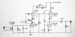
Phonodude achieves its amplification by using two MuF stages. It should be somewhat 70*100 (I think it is too much though). WCF stage gives you no voltage amplification. so you will have just 70*1. Will it be enough? In such case input transformer should have higher ratio.
The 5755 is less sensitive to heater than most . Average spec is +/- 5 % this tube gives +/- 10 % staying above 5.7 and below 6.3 should reduce noise both random and space charge as well as distortion . The only way is as df96 said is to build and measure . Then experimenting with CCS the heater VS reduced voltage is worth trying . Reference the heater about 45 volt above the cathode quiets it. Well at least it has in this tube for me.A cooler cathode will help with grid current. Try it. Make it too cool and the valve characteristics will change, eventually noise will rise as the shot noise smoothing provided by the space charge will disappear.
At the moment you have no way of controlling the overall gain. Also with 20dB gain in the transformer and about 37dB in the mu follower there's a definite chance of overloading the first tube. Also your total gain is 57dB which may be a little on the low side for a ribbon in some applications. Lastly the output stage has a very low output impedance which is probably unnecessary. You might like to think about splitting the gain between the two tubes and placing a level control between them and you could probably do with a 20dB switched pad before the transformer. For example you could change the first tube to a 6SN7 mu follower which will give you about 45dB of gain with the transformer, follow it with a pot and change the output stage to an SRPP which would give you up to 30dB additional gain should you need it plus is has an adequate drive capability.
Cheers
Ian
Cheers
Ian
@SY:
Cin = Cgk + Cgp*(A+1)
Cin = 1.8 + 1.4 (70 + 1)
Cin = 101.2pF
So if the 5755 tube itself has about 100pF, what does that mean for a LL1935 transformer?
http://www.lundahl.se/pdf/1935.pdf
@mm7 & Ruffrecords :
Perhaps for most applications I would be using this with, a Mu-Follower is appropriate for most scenarios. It is probably going to be pretty rare that a recording device or playback would require such a low impedance. The impedance of a Mu-Follower should suffice for most.
What I am interested is having a device that has Plenty of gain with lowest noise possible. (and least parts as possible). (lowest THD possible too!)
Ruffrecords, when you mention using a low gain tube like a 6sn7, it would be for the concept of balancing first and second stages for the sake of using a pot in-between?
And why end with an SRPP?
edit----
I plan on recording pretty damn quiet stuff with the mic I am making. I want to make sure that noise floor is delt with in an appropriate way. Better having too much gain right? (given that there is an attenuator somewhere). Where should that be specifically ?
Last edited:
A mic pre design is always a compromise between noise floor and headroom. Splitting the gain between several stages with attenuator between helps this. So yes, the idea of suggesting a 6SN7 was to split the gain between two stages with a pot in between. The big question is, is the first stage noise performance any better with a mu=70 tube than it is with a mu=20 tube. If you make the measurements you will find there is very little if any difference so it is rerasonable to split the gain between two stage to gainbetter headroom.
I suggested an SRPP for the output because it has gain and, unlike the mu follower, it has a true push pull output so its load driving capability is better.
If you are going to record really quiet stuff with a ribbon microphone then the first tube is going to compromise your noise floor and as I noted above it won't matter too much if the tube has a mu=70 or 20. The best way to improve noise performance is with gain before the first tube i.e. in the thransformer so I would suggest you look for one with, say, a 1:20 ratio.
Cheers
Ian
Cheers
Ian
The 5755 is designed to have a very low microphonic it self . To max the noise floor on that tube the heater need to be about 45 volt above the cathode . I do agree with ruffrecords that 5755 would not have much noise advantage over a 6sn7 all thing being done the same. Attention to heater voltage and it reference to the cathode is very important. If a very low floor is desired . Regards
- Status
- This old topic is closed. If you want to reopen this topic, contact a moderator using the "Report Post" button.
- Home
- Amplifiers
- Tubes / Valves
- Ribbon Microphone Preamp