I was eyeballing the 5755 because one could get away with a zero volt bias. (for noise reasons?) As well as I have a few at hand. So getting a 6sn7 with a more performance input transformer would definitely be advisable. Im looking around for somthing better than 1:10. Would Moving Coil transformers be good?
Luhndall stuff is expensive for their MC stuff.
On the Output SRPP stage, what kind of tube would you recommend? (For High transconductance?)
Also should I consider cathode bypassing for any of this? or is that just going to litter the crap with capacitor distortion
Luhndall stuff is expensive for their MC stuff.
On the Output SRPP stage, what kind of tube would you recommend? (For High transconductance?)
Also should I consider cathode bypassing for any of this? or is that just going to litter the crap with capacitor distortion
...Im looking around for somthing better than 1:10.
My understanding - the larger transformer ratio is the more ribbon is loaded (damped). This also depends on input impedance of a tube.
Damping the ribbon may impact sound.
Usually a ribbon mic already includes a transformer with a ratio about 1:37.
Adding another transformer with a ratio more than 1:10 should be well justified.
Especially if you are going to use grounded cathode that increases grid current / decreases impedance.
FYI. I've calculated signal/noise for 12AX7, 5755 and WE417A.
Signal was calculated for speech SPL (60dB), ribbon 2 inch length (0 thickness!), flux 0.25T.
Ribbon produced voltage 0.6uV.
Two transformers 1:37 and 1:10 multiplied the ribbon voltage 370 times to 0.23mV.
12AX7 and 5755 have 0.72uV of thermal noise and give 50dB between speech signal and their thermal noise.
WE417A has 0.18uV noise and gives 60dB between speech and noise.
The 5755 is designed to have a very low microphonic it self . To max the noise floor on that tube the heater need to be about 45 volt above the cathode . I do agree with ruffrecords that 5755 would not have much noise advantage over a 6sn7 all thing being done the same. Attention to heater voltage and it reference to the cathode is very important. If a very low floor is desired . Regards
You need to elevate the heaters in a mu follower anyway to keep Vhk within spec. dc heaters are pretty much essential too.
Cheers
Ian
I was eyeballing the 5755 because one could get away with a zero volt bias. (for noise reasons?) As well as I have a few at hand. So getting a 6sn7 with a more performance input transformer would definitely be advisable. Im looking around for somthing better than 1:10. Would Moving Coil transformers be good?
Luhndall stuff is expensive for their MC stuff.
On the Output SRPP stage, what kind of tube would you recommend? (For High transconductance?)
Also should I consider cathode bypassing for any of this? or is that just going to litter the crap with capacitor distortion
You need to look for a proper microphone transformer. MC and MM stuff is not really a suitable substitute. There are plenty of goo 1:10 mic transformers about but as you have discovered they are not cheap. 1:20 are rarer but you can sometimes find goo UTC ones.
I see no reason not to cathode bypass the mu follower. There is no real need to operate at zero bias - it only compromises headroom.
For the output SRPP I would recommend a 6922 or its Russian equivalent.
Cheers
Ian
FYI. I've calculated signal/noise for 12AX7, 5755 and WE417A.
Signal was calculated for speech SPL (60dB), ribbon 2 inch length (0 thickness!), flux 0.25T.
Ribbon produced voltage 0.6uV.
Two transformers 1:37 and 1:10 multiplied the ribbon voltage 370 times to 0.23mV.
12AX7 and 5755 have 0.72uV of thermal noise and give 50dB between speech signal and their thermal noise.
WE417A has 0.18uV noise and gives 60dB between speech and noise.
I think you mean shot noise rather than thermal noise. In practice flicker noise is a big contributor in the audio band and you will be lucky to achieve an EIN of 2uV with a 12AX7. I have not tried a WE417A but in practice 2.5/gm is nowhere near reality.
Cheers
Ian
True this tube is the quietest 45 above the cathode or there about , CCS the heater may help some with the quieting.You need to elevate the heaters in a mu follower anyway to keep Vhk within spec. dc heaters are pretty much essential too.
Cheers
Ian
Last edited:
Hi, Perhaps this may be a quick question:
So I am in the process of designing a ribbon microphone. I am getting alot of my info from "http://www.diyaudiocomponents.com" and was wondering what a suitable preamp would be for a 4mm wide 2.5u thick ribbon in between two neodymium magnets (2"x1/4"x1/4").
I'm posting this without reading all the other comments. So as not to be biased by them. Two things...
1) You need to transformer couple the mic. You should get as MUCH voltage gain as as you can with the transformer. Go for 1:10 if you can. But such a high ratio transformer will be a vary good "antenna" and will need double mu-metel shield. You can buy these for about $80 each they are built into a he metric can. For less money for about $20 Edcor makes a ribbon mic transformer. Place in inside a home made shield
2) pentodes are noisy. Do the first gain stage using a 12AX7 tube. For even less noise use both sections in parallel.
In short noise is the thing to avoid. Use shielded wire, star grounds and of course DC regulated heaters and even a regulated B+ supply if you can. You have to be nearly parodied about noise to keep hum and his out. The 1:10 transformer give you a NOISELESS gain of 10. But if not shielded and grounded will pick up hum. But 10x votage gain in the former mais you need that much less form a noisy tube. so it has the effect of reducing the total noise by 10x.
Last edited:
WE417A? I have been told a little bit about them. Recommended compared to the 12ax7? Or Hassle? Any ultimate solution for the input tube? (being that 1:10 input transformer would be a constant)
@ ruffrecords: goo transformers? What does that mean?
& Grounded Grid vs Cathode Bypass?
And I know there are debates on AC vs DC heaters, but say If I were to elevate either option, how negligible would AC heating actually be? I used AC heaters before and had pretty sweet luck so far. (I find joy in twisting solid core wire) & I have transformer convenience for 6.3v stuff.
WE417A? I have been told a little bit about them. Recommended compared to the 12ax7? Or Hassle? Any ultimate solution for the input tube? (being that 1:10 input transformer would be a constant)
@ ruffrecords: goo transformers? What does that mean?
& Grounded Grid vs Cathode Bypass?
And I know there are debates on AC vs DC heaters, but say If I were to elevate either option, how negligible would AC heating actually be? I used AC heaters before and had pretty sweet luck so far. (I find joy in twisting solid core wire) & I have transformer convenience for 6.3v stuff.
Although shot noise reduces with plate current, flicker noise does the opposite. Flicker noise also varies a lot from tube to tube so the only real answer to the quietest tube is to measure many and select the best. Having said that, the 6DJ8/ECC88/6922 has, as a rule, a lower measured absolute EIN than the 12AX7. It is probably worth paralleling the triodes in a ECC88 to improve noise performance although I have not tried it. Bottom line is the best I have been able to measure with either a 12AX7 or a 6CG7 (6SN7 in a B9A bottle) is about -125dBu which gives a noise figure of about 6dB relative to a 150 ohm source. Even a perfect amplifier would only be 6dB quieter.
With a mu follower, even with elevated heaters, one cathode is above the heater voltage and one is below. The one above the heaters can act like an anode and hence pass ac heater current so I would definitely recommend dc heaters for a mu follower.
A good transformer has sufficient primary inductance not to cause LF response to drop off before 20Hz, is wound in such a way as to minimize stray capacitance, especially on the secondary, so the HF performance is not compromised, is adequately screened from external magnetic fields and uses a core material that causes minimal distortion at the envisioned input levels. All these factors tend to increase cost. Manufacturers of good transformers include Sowter, Lundahl, Cinemag and Jensen. Manufacturers of cheaper transformers will skimp on one or several of the above e.g. Edcor,OEP.
Grounded grid is only useful for very small signals. Larger signals produce grid current and its attendant distortion. Also, bias conditions are more stable with conventional cathode bias (decoupled of course)
Cheers
Ian
I think you mean shot noise rather than thermal noise. In practice flicker noise is a big contributor in the audio band and you will be lucky to achieve an EIN of 2uV with a 12AX7. I have not tried a WE417A but in practice 2.5/gm is nowhere near reality.
Ian
Thanks Ian.
Well, if the theory fails, what in practice would be an input signal voltage that is equal to tube shot and flicker noises (for 12AX7. And what is the quietest tube?)?
So we can start from that "noise voltage" adding 80 or more dB using a proper transformer whatever ratio it will be required.
thanks!
Could Pete Millett's design be modified to get ribbon level amplification by reducing the feedback? It seems pretty similar to what has been described a page or two ago.
Thanks Ian.
Well, if the theory fails, what in practice would be an input signal voltage that is equal to tube shot and flicker noises (for 12AX7. And what is the quietest tube?)?
So we can start from that "noise voltage" adding 80 or more dB using a proper transformer whatever ratio it will be required.
thanks!
As I mentioned earlier, an EIN of about 2uV is the best you are likely to get with a 12AX7 which translates to about 0.2uV at the input of a 1:10 input transformer. To put that into context, it is normal to to refer noise performance to the Johnson noise in a typical microphone source resistance of 150 ohms which, in a 20KHz bandwidth happens also to be about 0.2uV. Hence my earlier contention that a noise factor of about 6dB would be achieved. As I said earlier, this is about -125dBu. If you add 80dB gain to this then the noise at the output will be -45dBu. Even a perfect, noise free amplifier would have an output noise of -51dBu.
Cheers
Ian
Thanks Ian, I see we need transformer and high gain.
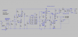
Here is new high gain preamp. First stage is 6N23P cascode, second 12AX7 mu-f, third is 6N23P SRPP. Overall gain is 84dB without input transformer. With it it is 103dB.
I have some issue here. First and second stages have very low THD: 1-st 0.004%, 2-nd 0.0005%. But third drastically drops to 0.07% whatever I do. It becomes a little bit better (0.025%) with 6N6P tube (with a little bit less gain).
How to improve THD of the 3-rd stage?
Attachments
wow, 84dB. That is thoroughly impressive. Does LTSpice produce ways of metering / gauging / displaying thermal noise? THD is renderable but I feel that noise may be an equal contributor to this whole battle. As ChrisA mentioned that transformers produce just about noiseless gain, I feel that this 84dB will be a little harmed by noise (although sufficient in signal gain).
I did just have a thought, if having a 1:20 transformer at the input may load down the ribbon, what if you stuck a transformer of large ratio somewhere in between the amplifying stages impedance can be more properly delt with by appropriate tube designs. Kind of in the same logic that an attenuator in the middle of the stages may do similar in noise & distortion etc. Is this a crazy thought?
I did just have a thought, if having a 1:20 transformer at the input may load down the ribbon, what if you stuck a transformer of large ratio somewhere in between the amplifying stages impedance can be more properly delt with by appropriate tube designs. Kind of in the same logic that an attenuator in the middle of the stages may do similar in noise & distortion etc. Is this a crazy thought?
Thanks Ian, I see we need transformer and high gain.
Here is new high gain preamp. First stage is 6N23P cascode, second 12AX7 mu-f, third is 6N23P SRPP. Overall gain is 84dB without input transformer. With it it is 103dB.
I have some issue here. First and second stages have very low THD: 1-st 0.004%, 2-nd 0.0005%. But third drastically drops to 0.07% whatever I do. It becomes a little bit better (0.025%) with 6N6P tube (with a little bit less gain).
How to improve THD of the 3-rd stage?
Distortion in triodes is proportional to signal level. The first two stages have very small signals so their distortion is understandably low. You nearly always get most distortion in the last stage. 0.07% is a very good figure for an SRPP. What was the output signal level and what load did you use?
By the way, 103dB of gain is far too much - you will be like to get a 20dB S/N ratio. I think you can do away with the middle stage.
Cheers
Ian
To woodrough.
LTSpice has some noise simulation, but I do not have knowledge how to use it. Need some training. Also I am not sure if tube models include everything for this noise simulation.
Idea of input transformer is to bring signal up to make it higher above tube self noise signal. On next stages signal is already high enough so tube noise may be ignored. It is my feeling and should be checked.
To put a transformer instead of mid stage? It interesting idea. I even saw somewhere transformer based attenuators.
But 1-st stage should be powerful enough to push through 1:100 transformer, and 2-nd stage should have very high input impedance.
Another thing, transformers do not produce noise, but on higher signals transformers bring other types of distortions.
To Ian,
if 0.07% is a very good figure for an SRPP is there a better topology?
Yes may be 104 dB is too much. That is why there is attenuator in the middle.
Woodrough mentioned about a need to amplify quiet sounds.
Most of mic sensitivity specs are based on 1Pa of sound pressure that is created by 90dB sound. It is quite loud sound. I've put speech level 60dB into a formula that is 0.02Pa SPL. It produces just 0.6uV on ideal ribbon (unfortunately I do not have ribbon mass in the formula). So real ribbon will produce less. Anyway, mic transformer 1:37 makes it 22uV.
Then following preamp stages amplify to:
Preamp input transformer - 220uV
Stage1 - 8mV
Stage2 - 0.55V
Stage3 - 7V
Again, it is for ideal ribbon.
Without mid stage it will be 64dB of total gain. Will it be enough for amplifying weak sounds without adding noises?
A wild idea, to make 2-nd stage switchable.
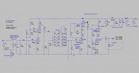
@mm7
You are probably not getting enough gain from the first stage. Try increasing the anode resistor and you definitely need to decouple the cathode resistor from the hum point of view.
Also I think you are running the SRPP at too high a quiescent current. 5mA is ample. At 15mA you are probably exceeding the tube's dissipation spec. You should also decouple the bottom cathode resistor. The transformer gives you 20dB gain, the cascode should be at least 30dB and the SRPP will be close to 30dB for a total of 80dB. 220uV is -73dBu so 80dB of gain is ample to raise this above 0dBu.
Both the SRPP and the cascode produce distortion because the top triode is a relatively low impedance load for the bottom one. The mu follower produces much less distortion because the top triode presents a high impedance load to the bottom triode. For minimum distortion you could use two stages of ECC88 mu followers each of which will have about 30dB of gain.
Cheers
Ian
Last edited:
Thanks Ian, I'll try.@mm7
You are probably not getting enough gain from the first stage. Try increasing the anode resistor and you definitely need to decouple the cathode resistor from the hum point of view.
I thought that bypassing just removes local NFB improving gain. And as soon as we already have plenty of gain with 3 stages we can sacrifice a little bit gain and also improve sound by removing caps.
Hum should be eliminated by heater elevation. Is it right?
6N23P has 20mA max@mm7
Also I think you are running the SRPP at too high a quiescent current. 5mA is ample. At 15mA you are probably exceeding the tube's dissipation spec.
220uV is after the input transformer. So it will be added by 60dB of tube's amplification, that gives -13dBu. Will it be enough? And again, it is for an ideal weightless ribbon. A real ribbon with mass will produce less voltage.@mm7
You should also decouple the bottom cathode resistor. The transformer gives you 20dB gain, the cascode should be at least 30dB and the SRPP will be close to 30dB for a total of 80dB. 220uV is -73dBu so 80dB of gain is ample to raise this above 0dBu.
Yes, and we go back again to PhonoDude! But someone here said that a mu-follower output cascade can work effectively only to one input impedance. that is why I've changed that to White follower, and then to SRPP.@mm7
Both the SRPP and the cascode produce distortion because the top triode is a relatively low impedance load for the bottom one. The mu follower produces much less distortion because the top triode presents a high impedance load to the bottom triode. For minimum distortion you could use two stages of ECC88 mu followers each of which will have about 30dB of gain.
May be it would make sense to change SRPP to White again?
- Status
- This old topic is closed. If you want to reopen this topic, contact a moderator using the "Report Post" button.
- Home
- Amplifiers
- Tubes / Valves
- Ribbon Microphone Preamp