It looks like RMAA does not support unweighted NL. But there is NL through frequencies chart above (third pic). Could you say about noise looking on that?
I cannot measure gain because I do not have uV-meter. But theoretical gain of the preamp is 84dB: 14dB from 1:5 tranny, 40 from first stage, 30 from second. And logarithmic volume attenuator was in the middle. That is how MuMu is set for recording from my ribbon microphone.
Should I measure MuMu with 100% volume and accordingly reduced input signal?
Ian, I am still puzzled regarding noise measurements. Tried to read whatever found in Net to get understanding. There couple of metrics: Noise Level (unweighted and weighted), Noise Floor, SNR by power, SNR by voltage, etc....
I thought that RMAA measures Noise Level (unweighted) automatically, regardless pot level I set. Are there rules/standards how measurements should be taken? Something like requirements to input signal level, volume pot level, output signal level?
How I've done measurements:
1) With a preferred input tranny config 1:5 and my ribbon mic, I've set volume pot level so peeks of signal reach -20dB (with sound card capture volume set to 100%).
2) Plugged sound card output into MuMu input and: adjusted sound card output volume to 30%; adjusted RMAA test sound file channel output volume to 30%. So altogether souncard output level is comparable with mic output.
3) Played the RMAA test sound file with recording it into anothher channel. Volume levels of the RMAA test sound file and the recorded file are close.
4) Saved recorded file with format WAV 24-bit, 44.1kHz.
5) Loaded the recorded file into RMAA and analyzed to produce metrics.
I believe it is a proper way to produce preamp metrics. Do you think NL metric is unrealistic? Could you advise how this metric should be measured?
Also, another question, RMAA shows NL is -63.2dBA, is it good, not good? What a good tube Hi-Fi mic preamp should show?
Thanks!
To measure noise you do not need to send a sound file. You just connect a 150 ohm resistor across the mic pre input and measure the noise at the output. You should do this at various gain settings but start with the gain at maximum. To work out the eqivalent input noise (EIN), which is what tells you if the mic pre is goo.d or not, you also need to measure the gain.
To measure the gain I suggest you make a 70dB attenuator from a 36K resistor and an 11 ohm resistor. First note the level you get when you do a loop back test. next connect the soundcard output via the attenuator to the mic input. Measure the mic pre output level and adjust the gain pot so the output level is the same as you got in the loop back test. You have now set the mic pre gain to 70dB.
Now disconnect the soundcard from the mic pre input and connect 150 ohms across the mic pre input. Now use RMA to measure the noise at the output. The EIN of the preamp is this level -70dB. You want to aim for a figure netter than -120dBu.
Cheers
Ian
RMAA works by comparing its Test file, that has all kinds of signals and also rests, quiet places, with a file recorded after being passed through a device(s).
It relies on synchro signal at beginning - 1000Hz for 1 sec, then compares further signals and rests as their wave's shapes and amplitudes.
I think it computes noise level when compares a rest - quiet piece (with all zeros) with whatever noise signal has been recorded at same place.
RMAA cannot measure just a signal from 150R. It requires two files of its specific signal shapes, original one and passed through a device one.
Is the way how RMAA measures noise is not correct? How to translate its NL 63.2dBA to EIN?
Another program should be used for this 150R method. But I do not have one. Though I can capture spectrum of 150R noise - level on each frequency from 0 to 50kHz. How to compute it to EIN?
OK, I did not realise that is how RMA works. The problem is that in the quiet parts the mic pre will amplify the noise from the sound card and give a false reading. It normaly measures devices with low gains where this is not a problem but it is not good enough to measure a mic pre. I would suggest you use the 70dB attenuator and then run RMA. The anu noise from the sound card in the quiet parts will be reduced by 70dB.
Cheers
Ian
Cheers
Ian
In metrics I have posted in http://www.diyaudio.com/forums/tubes-valves/234937-ribbon-microphone-preamp-42.html#post3740554 #415 the noise level of the sound card is -98.1dBA.
And the NL of MuMu is -63.2dBA. Am not sure how to subtract NL of the sound card from NL of the MuMu. ( -98.1 - -63.2 ) to get just MuMu NL.
May be (-130 - -98.1 + -63.2 ) = -95.1dBA ?
Also I tried to make attenuators as with R1 500k R2 1k, and other values for both. They brutally impacted frequency response, significantly rolled off LF andd HF. So I gave up and just reduced the card volume (hardware) -30dB and output channel volume (software) -40dB. That should give 70dB attenuation.
Last edited:
The problem is when the sound card noise measurement was made it was at unity gain. hen you test the mic pre you are adding 70dB of gain to this. The RMA will probably try to mute the sound card output and this may reduce the noise to a lower level but you don't want to measure the noise of your amplifier while it is amplifying the noise of another. That's is why I suggested using the 70dB attenuator. This gets the noise from the sound card well doen below that of the mic pre and also allows you to set the gain reasonably accurately.
Cheers
Ian
Cheers
Ian
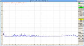
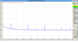
I've added snubbers to rectifier bridge - 0.1mF serial with 100R for each shoulder of the bridge. However it looks like it does not help. Even worse. I see some 60Hz harmonics where they were not seen before.
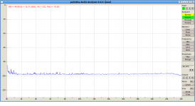
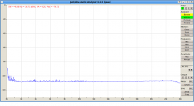
Please take a look at charts. It is noise from 150R pluggend into input XLR.
I am puzzled why there is the buzz. It is clear that this buzz (quite little, but still) comes from HT, because when I turn off mains transformer there is no buzz.
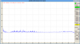
Also there is less buzz when bottom part of aluminum box is removed. I think that mains transformer induces some currents in the box when it is closed, so loop through the box is established. Last three pictures are noise with box open, no bottom part. V in file name is volume (clicks) on volume attenuator, 22 clicks - is full volume.
Please take a look at charts. It is noise from 150R pluggend into input XLR.
I am puzzled why there is the buzz. It is clear that this buzz (quite little, but still) comes from HT, because when I turn off mains transformer there is no buzz.
Also there is less buzz when bottom part of aluminum box is removed. I think that mains transformer induces some currents in the box when it is closed, so loop through the box is established. Last three pictures are noise with box open, no bottom part. V in file name is volume (clicks) on volume attenuator, 22 clicks - is full volume.
Attachments
Last edited:

The fact that the whole noise spectrum, including the hum goes up and down with the gain implies the hum is entering the first stage. To make sure it is not getting into the XLR socket itself, repeat the tests with the input short circuited.
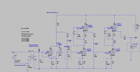
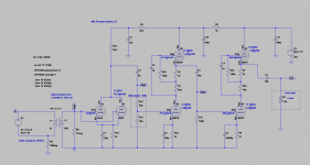
Looking at the schematic I notice the first stage rune from the same supply as the later stages. You would normaly need to inlcude some extra decoupling for the first stage to ensure HT noise to not get in. As your first stage is a simple CC one it has absolutely no power supply rejection at all so it badly need decoupling.
I notice also that all the stages are being run at relatively high current - the second seems to be at 13mA. There is not need for the second stage to run at such a high current and if my esticmates are right, you are droppoing 130 volts across the 10K resistor which is about 1.7 watts. My standard go to mu follower for a 6922 uses 220R cathode resostors and a 4K7 resistor between the tubes.
Cheers
Ian
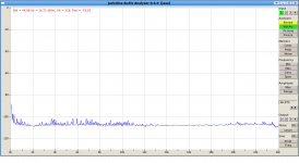
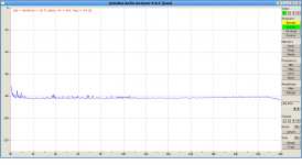
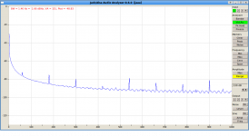
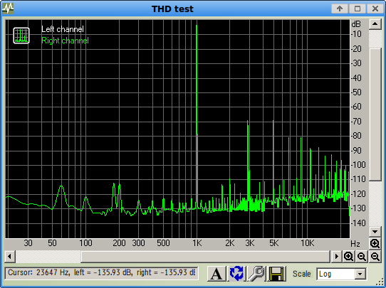
I've got snapshots of 150R up to 100Hz and up to 500Hz with higher resolution.The fact that the whole noise spectrum, including the hum goes up and down with the gain implies the hum is entering the first stage. To make sure it is not getting into the XLR socket itself, repeat the tests with the input short circuited.
Same with input short circuited. Pic 3 and 4.
Looking at the schematic I notice the first stage rune from the same supply as the later stages. You would normaly need to inlcude some extra decoupling for the first stage to ensure HT noise to not get in. As your first stage is a simple CC one it has absolutely no power supply rejection at all so it badly need decoupling.
I notice also that all the stages are being run at relatively high current - the second seems to be at 13mA. There is not need for the second stage to run at such a high current and if my esticmates are right, you are droppoing 130 volts across the 10K resistor which is about 1.7 watts. My standard go to mu follower for a 6922 uses 220R cathode resostors and a 4K7 resistor between the tubes.
This values are selected during multiple trials - target was to achieve minimal THD. If I set Rc higher it makes THD worse.
I assume because operating point shifts to more curve segment of tube characteristic.
What is your B+?
I've added decoupling RCs. I did not expect that their capacitors impact linearity some tricky way - LF rolls off if I increase capacitance. That is why C3 is 2.2uF.
BTW, what topology would be better for the first stage, this with paralleled 6922 or mu-follower? From noise and other perspectives?
Attachments
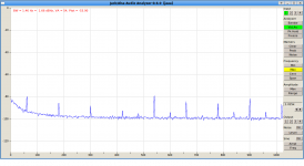

I've got snapshots of 150R up to 100Hz and up to 500Hz with higher resolution.
Same with input short circuited. Pic 3 and 4.
Thanks for the extra hi res plots. These seem to show 60Hz and 180Hz as the first two peaks. The 60Hz implies this is not an HT problem but rather a transformer coupling problem which would also go away when the mains is turned off.
This values are selected during multiple trials - target was to achieve minimal THD. If I set Rc higher it makes THD worse.
I assume because operating point shifts to more curve segment of tube characteristic.
What is your B+?
I would not rely on simulations to set operating points for absolute minimum distortion. They are very unreliable. The absolute levels and the relationship between harmonics are never achieved in the real circuit. My B+ is 300V.
The other problem with running at high plate currents is that the grid bias voltage becomes very low - less than one volt in both your mu follower stages. This means you will run into grid current distortion much earlier than a stage biased at a lower current. I don't know of any spice model that accurately models grid current.
I've added decoupling RCs. I did not expect that their capacitors impact linearity some tricky way - LF rolls off if I increase capacitance. That is why C3 is 2.2uF.
You are seeing the increase in gain of the CC stage due to the increase in the effective plate resistance as the decoupling loses its effectiveness at low frequencies. Once again you are running at a rather high current. The problem with that in a CC stage is it means you use a lower plate resistance which lowers the stage gain and in this stage you want all the gain you can get.
BTW, what topology would be better for the first stage, this with paralleled 6922 or mu-follower? From noise and other perspectives?
The paralleled 6922s should be better from the noise point of view but the the mu follower has better power supply rejection ratio an lower distortion.
Cheers
Ian
Ian thank you for looking into all of this and helpful advises.Thanks for the extra hi res plots. These seem to show 60Hz and 180Hz as the first two peaks. The 60Hz implies this is not an HT problem but rather a transformer coupling problem which would also go away when the mains is turned off.
Yes, when I disconnect mains, the preamp runs on power accumulated in reservoir caps, there is no buzz. I tried to put thick soft steel ring over the mains transformer (toroidal one), hoping that it will gather magnetic field into it. It does not help.
So I do not know. Snubbers do not help, shielding does not, iron ring does not. I think the only option is left - to separate PSU from preamp.
I do not think that distortion can be an issue in first stage where greed voltages are so low. supply rejection ratio yes....
The paralleled 6922s should be better from the noise point of view but the the mu follower has better power supply rejection ratio an lower distortion.
I've put decoupling RC, should it help?
Here is next version with increased Rc. What do you think?
How much dB of noise improvement can be achieved with paralleled CC versus mu-follower?
I cannot find data on tubes noise, like a list of tubes with their noises. To choose from. As I understand, the high gm is a key factor. That is why 6922 is used. But there are tubes with even higher gm. Why they are not much in use? I read about one exotic preamp with a dozen(!) or so 6S45P in parallel.
Review: NVO SPA one Phono Preamplifier | Confessions of a Part-Time Audiophile
nvoaudio
Does it make sense to look in this direction?
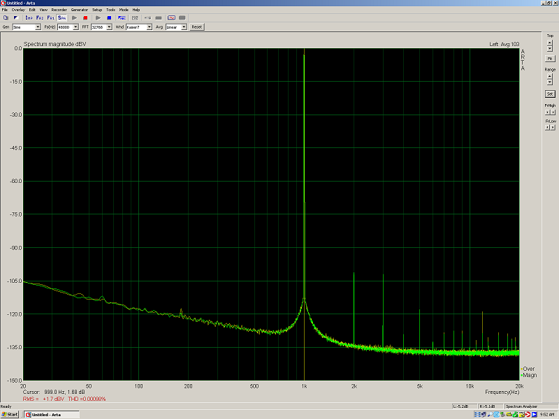
I've made loopback test for EMU 0404 soundcard.
FR curve matches very closely with what was captured from the MuMu preamp. Conclusion - RF of the preamp is flat.
Here is sound for all input configs, and loopback test metrics.
I suggest that FR and THD of the preamp are very good. Noise level (currently 78dB) and accordingly dynamic diapason may be improved.
Sorry to butt in... but comparing your loopback result with this one - they look very different... May be the settings were different? (can that happen in a loopback test?)
The simple way to determine if it is magnetic coupling is to remove the transformer and connect it with flying leads. If the hum goes away you have found the cause.
There is no real data on which tubes produce the lowest noise. Few manufactures even mention it in their data sheets, and where they do it is at MHz frequencies not audio ones. There is also a lot of folklore surrounding its calculation. Most people simply quote the standard 2.5/gm formula for shot noise which explains why high gm tubes are usually recommended. My own measurements of lots of tubes have shown that the 2.5/gm formula produces overly optimistic figures. I think the reason for this is another source of noise at audio frequencies called flicker noise. Rather than being broadband noise like shot noise, flicker noise has a 1/f characteristic and is sometimes called excess noise.
Shot noise is inversely proportional to gm and gm is proportional to plate current so people recommend running a high gm tube at a high current to get low noise. Unfortunately, flicker noise is proportional to the square of the plate current so setting a high current actually increases flicker noise. My own tests have shown that the actual noise from triodes is at least twice what it should be when calculated by the 2.5/gm formula so it looks like flicker noise is important at audio frequencies. As you increase plate current, shot noise will go down but flicker noise will go up. Somewhere there is an optimum current for a tube.
Unfortunately, flicker noise is not well understood but is thought to be generated mainly by imperfections in the cathode material. For this reason it varies a lot from tube to tube of the same type. That's why, in the old days, tubes for use in the mic pres of broadcast mixers were selected for low noise.
The bottom line is that, of all the tubes I have tested, the ECC88/6922 is consistently lower noise than any other tube I have tested. In theory, using two in parallel should reduce the noise they produce by 3dB. However, I think going any further than that is a waste of time. With a decent input transformer, it is not too hard to make a tube mic preamp with and equivalent input noise of -125dBu. This is only 6dB noisier than the inherent noise from the 150 ohm equivalent resistance of your ribbon microphone. This means that no matter what you do you cannot improve the signal to noise ratio by more than 6dB. At this level it is more important to keep out external interference by paying attention to screening and grounding and keeping power supplies away from sensitive input circuits.
Cheers
Ian
Sorry to butt in... but comparing your loopback result with this one - they look very different... May be the settings were different? (can that happen in a loopback test?)
Everything may impact sound - computer PSU, Wi-Fi router ...
It will be lots of work to remove it from my layout, but I'll try.The simple way to determine if it is magnetic coupling is to remove the transformer and connect it with flying leads. If the hum goes away you have found the cause.
I also will try to reduce current through tubes, as you suggest that creates flicker noise.
I also thought how that can be that more powerful flow of electrons should create less noise. It was counter-intuitive to me, but you have explained - there are different types of noise. Now it is clear. Thank you.
Also reduced current may reduce transformer noise.
The bottom line is that, of all the tubes I have tested, the ECC88/6922 is consistently lower noise than any other tube I have tested. In theory, using two in parallel should reduce the noise they produce by 3dB. However, I think going any further than that is a waste of time. With a decent input transformer, it is not too hard to make a tube mic preamp with and equivalent input noise of -125dBu. This is only 6dB noisier than the inherent noise from the 150 ohm equivalent resistance of your ribbon microphone. This means that no matter what you do you cannot improve the signal to noise ratio by more than 6dB. At this level it is more important to keep out external interference by paying attention to screening and grounding and keeping power supplies away from sensitive input circuits.
Input transformer ratio has its limitations too. I've found that 1:10 severely impacts frequency response.
Ribbon is only 1 turn of conductor. It produces EMF that is so weak that it cannot be infinitely leveraged by transformers.
In my case ribbon is connected to 1:37 transformer in mic, and then it is connected to 1:5 transformer in preamp.
It is in total 1:185 transformer. Even with 1MegR of preamp input impedance it looks it is quite a load for the ribbon.
- Status
- This old topic is closed. If you want to reopen this topic, contact a moderator using the "Report Post" button.
- Home
- Amplifiers
- Tubes / Valves
- Ribbon Microphone Preamp