woodrough,
consider to make whole PSU in a separate remote box, especially if you are going to use EI transformer(s).
I've placed H+ PSU into same preamp box because mains transformer is toroid.
And still I had to shield input transformer, input wires and switches, everything that is between input XLR and first tube grid.
good luck! Let me know when you build it.
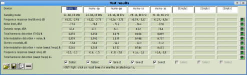
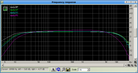
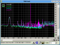
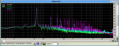
I've analyzed metrics with RightMark Audio Analyzer.
Here are metrics and graphs for different input transformer configurations.
BP - bypass transformer
SP - primary coils serial, secondary coils parallel - 1:2.5
PP - primary coils parallel, secondary coils parallel - 1:5
SS - primary coils serial, secondary coils serial - 1:5
PS - primary coils parallel, secondary coils serial - 1:10
Conclusions:
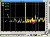
- THD 0.06% is not bad.
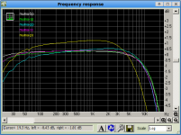
- Frequency Response is mediocre, and for 1:10 is poor.
- PP 1:5 should not be used. Use SS instead.
- Increasing ratio does not significantly help to reduce noise. Though I hear it reduced.
Question. Why Frequency Response rolls off after 10KHz?
Poor capacitors?
Though, wait, I did not test my sound card....
Here are metrics and graphs for different input transformer configurations.
BP - bypass transformer
SP - primary coils serial, secondary coils parallel - 1:2.5
PP - primary coils parallel, secondary coils parallel - 1:5
SS - primary coils serial, secondary coils serial - 1:5
PS - primary coils parallel, secondary coils serial - 1:10
Conclusions:
- THD 0.06% is not bad.
- Frequency Response is mediocre, and for 1:10 is poor.
- PP 1:5 should not be used. Use SS instead.
- Increasing ratio does not significantly help to reduce noise. Though I hear it reduced.
Question. Why Frequency Response rolls off after 10KHz?
Poor capacitors?
Though, wait, I did not test my sound card....
Attachments
Question. Why Frequency Response rolls off after 10KHz?
Poor capacitors?
Though, wait, I did not test my sound card....
It is called the 'Miller Effect'. Look it up on line and I think you will understand.
Cheers
Ian
I used Improved Tube models by Norman Koren.
For 12AX7 there is GP capacitance specified 2.4pF.
CGP multiplied by 100 is 240pF.
Plus CCG, 2.3P should give ~ 243pF of Miller capacitance.
If I put such cap between grid and anode of first lower tube and run analysis, HF rolls off 3dB starting from 800Hz! Given serial R of LL1935 secondary is 1300.
But without this "additional Miller" cap, HF drops 3dB at 60kHz!
Does it mean LTSpice/model calculates wrong?
the model:
.SUBCKT 12AX7 1 2 3 ; P G C; NEW MODEL
+ PARAMS: MU=100 EX=1.4 KG1=1060 KP=600 KVB=300 RGI=2000
+ CCG=2.3P CGP=2.4P CCP=.9P ; ADD .7PF TO ADJACENT PINS; .5 TO OTHERS.
E1 7 0 VALUE=
+{V(1,3)/KP*LOG(1+EXP(KP*(1/MU+V(2,3)/SQRT(KVB+V(1,3)*V(1,3)))))}
RE1 7 0 1G
G1 1 3 VALUE={(PWR(V(7),EX)+PWRS(V(7),EX))/KG1}
RCP 1 3 1G ; TO AVOID FLOATING NODES IN MU-FOLLOWER
C1 2 3 {CCG} ; CATHODE-GRID
C2 2 1 {CGP} ; GRID=PLATE
C3 1 3 {CCP} ; CATHODE-PLATE
D3 5 3 DX ; FOR GRID CURRENT
R1 2 5 {RGI} ; FOR GRID CURRENT
.MODEL DX D(IS=1N RS=1 CJO=10PF TT=1N)
.ENDS
Last edited:
Spice gets it right. The 243pF is between grid and ground not plate and grid. Basically the Miller effect multiplies the Cgp by the open loop gain (which in your case is pretty close to mu = 100) and connects it from grid to ground. I seem to remember you already have 47pF from grid to ground so you have about 300pF across the input.
However, this should not be a problem because it forms an RC network with the source impedance whic, even with a 1:10 transformer, should be no more than 15K ohms. This would have a -3dB point at about 35KHz so that does not explain the problem. For the roll off to start at 10KHz impies a much bigger source impedance or input capacitance. Are you sure the 47pF you fittted is not 470pF?
Cheers
Ian
Thanks Ian! You've saved me from remodeling it to a cascode. ")
I am not sure today what that is, 47 or 470. It well can be. In Sayal they often misplace stuff. I'll double check.
It is mica dipped, not too big size, like 1/4". should be around 50pF.
I'll double check.
If this cap is correct one, do you have other ideas?
May be it is measuring artefact?
Did you listen recording attached previosly? Does it sound dull, or like it rolls off from 6kHz?
Thanks!
BTW. My sound card is EM-U 0404 PCI.
Its analog metrics:
ANALOG LINE INPUTS
Type Unbalanced, low-noise input circuitry
Level Consumer: -10 dBV nominal, 6.4 dBV maximum
Frequency Response 20 Hz - 20 kHz: +0.20/-0.10 dB
THD + N -100 dB (.001%) 1kHz at -1 dBFS
SNR 111 dB (A-weighted 22kHz BW)
Dynamic Range 111 dB (1kHz, A-weighted, 22kHz BW)
Channel Crosstalk < -120 dB, (1 kHz signal at -1 dBFS)
Input Impedance 3.3K ohm
ANALOG LINE OUTPUTS
Type Unbalanced, low-noise circuitry
Level Consumer: -10dBV nominal, 6.4dBV maximum
Frequency Response +0.05/-0.10 dB, (20 Hz - 20 kHz)
THD + N -100 dB (.001%) 1kHz signal at -1dBFS
SNR 116 dB (A-weighted, 22 kHz BW)
Dynamic Range 116 dB (1 kHz, A-weighted, 22 kHz BW)
Stereo Crosstalk < -109 dB, (1 kHz signal at -1 dBFS)
Output Impedance 560 ohms
The 3.3K input impedance of your soudn card might be an issue. The output impedance of the 6n23 stage is probably around 1.5K so 3.3K is quite a load for it. Distortion could be quite high but should be OK with a normal 10K load. Might be an idea to test it with a 10K resistor in series with the input The 10Uf output cap and the 3.3K turnover at about 5Hz (-3dB) so you will probably be 1 dB down at 10Hz. Not a problem but the phase shift might cause bass muddiness.
Any easy way to check if the 47pF is the problem is to remove it and test again.
I have not listened to the recording. I'll do that now.
Cheers
Ian
Any easy way to check if the 47pF is the problem is to remove it and test again.
I have not listened to the recording. I'll do that now.
Cheers
Ian
they specify input impedance 3.3K. But I've measured its serial resistance, it is 10K. What should I take as Rload for LTSpice calculations?The 3.3K input impedance of your soudn card might be an issue.
Regarding output impedance I read somewhere and calculated in excel spreadsheet that mu-follower impedance is low. If I remember right, it was somewhat 200-300 Ohms.
Yes, I've found it - tube_pag1_v2.0.xls, downloaded from somewhere.
Zout is 140 Ohm, but for SRPP, it does not calculate Zo for mu-follower.
I plug regular headphones into output at it works quite well.
Juicy bass is what I like. But I like crisp highs as well. It needs more HF definitely.
Last edited:
they specify input impedance 3.3K. But I've measured its serial resistance, it is 10K. What should I take as Rload for LTSpice calculations?
How did you do that? The input is usually capacitor coupled.
Regarding output impedance I read somewhere and calculated in excel spreadsheet that mu-follower impedance is low. If I remember right, it was somewhat 200-300 Ohms.
Yes, I've found it - tube_pag1_v2.0.xls, downloaded from somewhere.
Zout is 140 Ohm, but for SRPP, it does not calculate Zo for mu-follower.
Zout for a mu follower is much higher, probably 3 or 4 times the value for the SRPP. When I did my early mu follower tests with the 6CG7 I measured Zout. It was 1500 ohms.
Cheers
Ian
Yea, understood.How did you do that? The input is usually capacitor coupled.
. I just measured R with multimeter. Here The Valve Wizard -Mu FollowerZout for a mu follower is much higher, probably 3 or 4 times the value for the SRPP. When I did my early mu follower tests with the 6CG7 I measured Zout. It was 1500 ohms.
they wrote:
so, for 6922 Ri is 2650. 2650/32.5 = 81.5 ! Wow, that low!Output impedance: The output impedance from the upper output (upper tube cathode (mm7)) is simply that of the cathode follower, which can be closely approximated as:
Zout = ra/mu
How to measure it? If it is really too high I need to take some measures...
Yea, understood.
Here The Valve Wizard -Mu Follower
they wrote:
so, for 6922 Ri is 2650. 2650/32.5 = 81.5 ! Wow, that low!
How to measure it? If it is really too high I need to take some measures...
The valve wizard figure is the theoretical small signal output impedance. Ri is not 2650 unless you are operating at the same point it was measured by the the manufacture. Even then, the value given is the static value and you need the dynamic value which is usually higher. The real Zout value is is therefore somewhat higher than theory suggests. Even it is was that low, you have to remember that output impedanace does not determine drive capability. That is set mainly by the quiescent current.
To measure it you need a high impedance measuring instrument like a DVM. Set the output to about 5V rms with no load connected. Then connect a 3K resistor load and without changing anything, measure the output again. it will be less than 5V rms due to the output impedance. I am sure you can work out the math to calculate the real Zout.
Cheers
Ian
The output impedance of a mu-follower is slightly higher than a CF using the same valve at the same bias point. How much higher depends on the ratio of the anode resistor to the anode impedance of the lower valve. In the case of an SRPP, where the anode resistor is small, the output resistance is more like Ra/3 than Ra/mu.
When considering SRPP and mu-follower you need to distinguish between output impedance and optimum load impedance (for balanced push-pull i.e. minimum even-order distortion) as they are not the same value unless you specifically design for this - but both are sometimes called Zout. Typically an SRPP has much higher output impedance than optimum load impedance, so the optimum loaded gain is much smaller than the unloaded gain. The mu-follower brings them closer. However the SRPP is rarely used these days with an optimum load and has become little more than a (Chinese) audio fashion.
When considering SRPP and mu-follower you need to distinguish between output impedance and optimum load impedance (for balanced push-pull i.e. minimum even-order distortion) as they are not the same value unless you specifically design for this - but both are sometimes called Zout. Typically an SRPP has much higher output impedance than optimum load impedance, so the optimum loaded gain is much smaller than the unloaded gain. The mu-follower brings them closer. However the SRPP is rarely used these days with an optimum load and has become little more than a (Chinese) audio fashion.
Are you sure? I would put it the other way round. SRPP Zout is typically Ra/3 or thereabouts. Mu-follower can approach Ra/mu.ruffrecords said:Zout for a mu follower is much higher, probably 3 or 4 times the value for the SRPP. When I did my early mu follower tests with the 6CG7 I measured Zout. It was 1500 ohms.
Last edited:
Are you sure? I would put it the other way round. SRPP Zout is typically Ra/3 or thereabouts. Mu-follower can approach Ra/mu.
I am probably comparing apples with pears. The 6CG7 mu follower was definitely measured at 1500 ohms. mu is 20 and at the 5mA operating point, Ra was about 10K so Ra/mu is 500R. So the measured Zout was around Ra/6.6.
The SRPPs I have tested have all been with the 6922. Ra is much lower than the 6CG7 and mu is much higher which tends to result in a lower Zout than for the 6CG7 mu follower but I have not measured it.
Cheers
Ian
OK. Just to explain my reasoning:
For SRPP or mu-follower (which are the same circuit apart from bias details) the output impedance can be found by dividing the open-circuit output voltage by the shorted output current. For a given input, the output voltage is somewhere between mu (mu-fol) and mu/2 (balanced SRPP). This is because the upper valve acts as an active load.
The output current is given by lower valve voltage gain into the anode resistor Ra, multiplied by upper valve gm. The active load has disappeared because of the output short. So circuit transconductance is mu x gm x Ra /( Ra + ra ). ra is anode impedance.
Doing the division gives Zout = (Ra+ra)/(Ra x gm) ( with an extra factor of around 0.5 for SRPP)
For SRPP Ra is typically somewhere in the region of 1/gm, and is much smaller than ra, hence Zout = ra/2 (or mu/(2gm) ). Ra of 2/gm gives Zout = ra/4.
For mu-follower Ra may be somewhere around ra so Zout = 2/gm (or 2ra/mu). Large Ra could push it down nearer 1/gm.
These estimates should be OK to within a factor of 2. Useful for the early stages of design. Later you need either the full maths or a good simulator.
Taking your 6CG7 mu-follower example: Ra=10k, ra=10k, mu=20, gm=2mA/V. The formula gives Zout=1k. A 6CG7 SRPP (with Ra=1k) would give Zout=2.5k.
OK. Just to explain my reasoning:
For SRPP or mu-follower (which are the same circuit apart from bias details) the output impedance can be found by dividing the open-circuit output voltage by the shorted output current. For a given input, the output voltage is somewhere between mu (mu-fol) and mu/2 (balanced SRPP). This is because the upper valve acts as an active load.
The output current is given by lower valve voltage gain into the anode resistor Ra, multiplied by upper valve gm. The active load has disappeared because of the output short. So circuit transconductance is mu x gm x Ra /( Ra + ra ). ra is anode impedance.
Doing the division gives Zout = (Ra+ra)/(Ra x gm) ( with an extra factor of around 0.5 for SRPP)
For SRPP Ra is typically somewhere in the region of 1/gm, and is much smaller than ra, hence Zout = ra/2 (or mu/(2gm) ). Ra of 2/gm gives Zout = ra/4.
For mu-follower Ra may be somewhere around ra so Zout = 2/gm (or 2ra/mu). Large Ra could push it down nearer 1/gm.
These estimates should be OK to within a factor of 2. Useful for the early stages of design. Later you need either the full maths or a good simulator.
Taking your 6CG7 mu-follower example: Ra=10k, ra=10k, mu=20, gm=2mA/V. The formula gives Zout=1k. A 6CG7 SRPP (with Ra=1k) would give Zout=2.5k.
I think I follow. What are ra and Ra in this context? Are they meant to be plate resistance ra and plate load Ra or something different? Ra for me is confusiing as I tend to use it for static plate resistance and Rl for the plate load resistance.
Forget that, I just read the post more closely.
Cheers
Ian
Last edited:
Not sure about the SRPP. ra at 5mA and 150V for the 6922 is about 5K for which Ra is about 680 ohms which gives Zout around 1K6 before the 0.5 factor. In my designs, there is no optimum load and the bottom cathode is bypassed. Stage gain is much larger than mu/2 so Zout is probably 800 ohms or so. Which explains why I think SRPPs have a lower output Z.
Interesting discussion. Thanks.
Cheers
Ian
Interesting discussion. Thanks.
Cheers
Ian
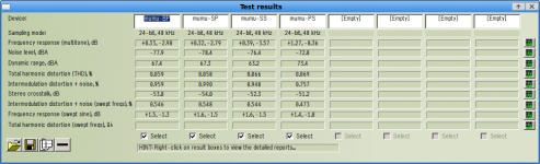
I've removed grid "47p" cap. I think HF improved dramatically. So it was higher capacitance. (Some issues (pf-pf) appear because of it in tranny bypass mode.)
Here are new metrics and sound.
Here are new metrics and sound.
Attachments
- Status
- This old topic is closed. If you want to reopen this topic, contact a moderator using the "Report Post" button.
- Home
- Amplifiers
- Tubes / Valves
- Ribbon Microphone Preamp