Thanks, Ian.
Is it normal? Or here is a way for improvement?
All resistors (except those in PSU) are metal film Dale, including stepped attenuator.
Tube is 12AX7 Tung Sol.
I suggest that a good input transformer 1:5 or may be 1:10 (though it is risky to loose bandwidth) should bring signal above noise.
Do you see any other measures that could be taken?
Thanks, Ian.
Is it normal? Or here is a way for improvement?
All resistors (except those in PSU) are metal film Dale, including stepped attenuator.
Tube is 12AX7 Tung Sol.
I suggest that a good input transformer 1:5 or may be 1:10 (though it is risky to loose bandwidth) should bring signal above noise.
Do you see any other measures that could be taken?
The overall noise performance is usually determined by the noise performance of the first amplifying stage. If you do not have a transformer then the first stage is the first tube. Tubes do not make good low noise first stages for this type of application. A good 1:10 input transformer will have a noise figure of about 1dB and increase your output level by 20dB without introducing much noise. Your overall S/N ratio will be much improved.
Cheers
Ian
Well, these "pf-pf" noises were from poor input cable. No pf-pf with good even much longer cable.
For heaters I use cheap 12V 2.5A SM PSU. External, without any additional filtration.
Following mp3 is how it sounds now.
It sounds quite good to me already. But I will order LL1935 transformer and try to place it on input in 1:5 or 1:10 configuration.
Will see. I mean - will hear") .
.
BTW. To moderator: is it possible to upload sound files directly without zipping?
It is funny that sound files cannot be uploaded in diyaudio forum.
For heaters I use cheap 12V 2.5A SM PSU. External, without any additional filtration.
Following mp3 is how it sounds now.
It sounds quite good to me already. But I will order LL1935 transformer and try to place it on input in 1:5 or 1:10 configuration.
Will see. I mean - will hear
.BTW. To moderator: is it possible to upload sound files directly without zipping?
It is funny that sound files cannot be uploaded in diyaudio forum.
Attachments
Added input transformer LL1935.
It picks up lots of buzz from PSU. When I turn off power, amp still works form reservoir caps for a minute or another. No buzz.
I've put three 4P2T switches to switch input into following configurations:
BP - bypass transformer, input goes directly to grid.
SP - transformer 1:2.5. Primary windings serial, secondary parallel.
PP - transformer 1:5. Primary windings parallel, secondary parallel.
SS - transformer 1:5. Primary windings serial, secondary serial.
PS - transformer 1:10. Primary windings parallel, secondary serial.
I compared sound in all configs with PSU turned off, to remove buzz.
Of course, BP sounds most natural, but weak and has barely audible Pf-Pf noises from cable/environment, masked by white/pink noise.
SP sounds very natural, no Pf-Pf noise.
PP and SS, sounds a little bit dry.
PS is hot, but sounds more dry. LF is impacted, but still can be used for some applications, where bass should be suppressed.
Each config allowed me to reduce volume 2 clicks (my log attenuator has 22 clicks), that audible reduced noise.
Conclusion - transformer helps but most likely will require to separate PSU from preamp completely, because input transformer and switches pick up buzz from mains transformer. I'll try to wrap input transformer and switches into aluminum box, but have little hope that it will help.
This is very interesting findings for sure.
On one of my previous projects, I was bench testing a circuit and kept getting disappointed by the looming hum. But because of my crowded bench top, I never properly explored the idea of moving the (isolated) PSU further than a foot away. Once it passed the 1.5 foot mark form the actual amps, the hum diminished amazingly. I could only assume it was because of the gigantic output transformers being a little to close to the power transformer. fields of flux etc.
Do you have recordings of this latest test? Im curious to hear the differences in 'texture' between the different ratios or w/ out transformer all together.
LL1935 is located in 4-5 inches from toroid mains transformer.
I assume LL1935 core magnetically couples with mains transformer.
Is there a chance to decouple it with using aluminum or copper shielding, without using expensive mu-metal shielding?
I'll try, but I have a bad feeling that I will have to assemble it again in 2 pieces: PSU and Preamp.
woodrough, I did not record sound this time. working on shielding....
Another idea. As the input transformer and switches circuit is completely passive, it can be easily separated from the preamp into its own box and placed closer to mic, farther from PSU.
The box can be done as multilayer iron and copper tubes with covers, something like that. Though, my mic is just one layer copper tube, and 1:37 transformer inside it does not pickup anything, even it is placed very close to PSU. Just tested. Brought bottom end of the mic, where 1:37 tranny is, to the mains transformer. No buzz. Does it mean just a copper shielding should work? So aluminum should do?
The box can be done as multilayer iron and copper tubes with covers, something like that. Though, my mic is just one layer copper tube, and 1:37 transformer inside it does not pickup anything, even it is placed very close to PSU. Just tested. Brought bottom end of the mic, where 1:37 tranny is, to the mains transformer. No buzz. Does it mean just a copper shielding should work? So aluminum should do?
I've made shielding box out of aluminum sheet. Buzz become more like a hum, but still is very audible.
I've recorded how it sounds.
Configs are: BP, SP(1:2.5), PP(1:5), SS(1:5), PS(1:10).
I'd say I am quite disappointed with the results. LL1935 impacted linearity, especially in high ratio configs. Sound is dry and harsh, no liveliness, no juices. Low ratio SP (1:2.5) sounds OK, but is even quieter than bypass, so no point to use it.
I think mic's transformer 1:37 has already high ratio, and increasing it will impact linearity. The key is to increase mic's performance, by using lighter foil, more powerful magnets or whatever.
Attachments
I've found new mic transformer LL1927A at Lundahl site. It has ratios 1+1 : 55+55. It is mentioned -
"The LL1927A is a very high turns ratio transformers for
active ribbon microphones."
What does it mean? Active mics have a preamp inside. But it is still a preamp. How it should be different with a standalone preamp?
May be I should upgrade my 1:37 mic's tranny LL1913 with this LL1927A beast in 1:55 or even 1:110 config?
wow, thats amazing how dry the sound becomes for not that much noise reduction. Hard to tell if its worth it to have an input transformer in the first place (even from the famed LL's). Is this right?
I would like to take a look at input tube design. Hunting a tube that is meant for delicate signals with low thermal noise values. Is there such a thing better than the 12ax7 / 12au7 etc tubes?
I would like to take a look at input tube design. Hunting a tube that is meant for delicate signals with low thermal noise values. Is there such a thing better than the 12ax7 / 12au7 etc tubes?
Added 0.1uF WIMA cap. I do not hear a dramatic change in sound. So grid DC current does not magnetize core.
So it looks like my ribbon motor via LL1913 1:37 has too high impedance for LL1935.
Using LL1927A in 1:110 ratio will require an impedance matching active stage, such as emitter follower, before long cable, or cable will pick up noise. With a very short cable it may be OK to plug it directly, Per Lundahl wrote.
I am thinking to give it a try in 1:55 ratio at least.
Attachments
Actually, after reviewing the wiring, I've found that I've wired wrong polarity for coils so they worked counter-phase. LL1935 has unusual pinout for coils: +- -+. I've wired it as +-+- by mistake. 
That is why sound was so dry, LF was simply cancelled.
Now there is lots of LF. And buzz has disappeared as well. I think now buzz is cancelled.
Here is new recording. Pink noise there is mostly from room acoustic enwironment, I believe - computer fan etc. Because, if I unplug the mic from cable, most of noise disappears and tube hiss is barely audible at level 14.
Also mic cable is quite long - 10ft. I need to buy a short one.
I've removed input serial 0.1uF cap.
I will postpone to degauss the tranny, unless Per Lundahl will recommend.
Attachments
These "great findings" are results of my poor attention to details. This is how actually it should be in the first place.
Yes, I like how it sounds now. It is main thing. But I am thinking to measure some characteristics, like THD, FR, SNR, to see an objective picture. Though I know, these metrics alone often do not explain why humans like how one device sounds and dislike another despite the metrics of the latter are same or even superior. But anyway these conventional metrics show what class a device belongs to.
I know that the core may be not saturated, but rather permanently magnetized, because I've measured resistance of coils with regular multimeter. A multimeter creates DC through a measured object to measure its resistance. This DC may leave, and, most likely, has left the mu-metal core magnetized in one direction to some degree.
Though my perception of LF tells me this possible magnetization, if exists, is on low level, that can be ignored.
How to demagnetize. I've asked Per Lundahl how to do it. He advised "You can use 2V RMS on the low impedance side and sweep frequency 100Hz - 10Hz - 100Hz a couple of times. Stop at 100Hz or higher.".
Also he said that there is no harm in "just in case" demagnetization.
I did not do that yet because I do not have a sound generator. I need to find a program for Linux, or write a simple one myself.
I have couple of schematics with and without PSU, with and without the input transformer.
I'll update one and publish soon. But there are no major changes in preamp core.
This is how actually it should be in the first place.Yes, I like how it sounds now. It is main thing. But I am thinking to measure some characteristics, like THD, FR, SNR, to see an objective picture. Though I know, these metrics alone often do not explain why humans like how one device sounds and dislike another despite the metrics of the latter are same or even superior. But anyway these conventional metrics show what class a device belongs to.
I know that the core may be not saturated, but rather permanently magnetized, because I've measured resistance of coils with regular multimeter. A multimeter creates DC through a measured object to measure its resistance. This DC may leave, and, most likely, has left the mu-metal core magnetized in one direction to some degree.
Though my perception of LF tells me this possible magnetization, if exists, is on low level, that can be ignored.
How to demagnetize. I've asked Per Lundahl how to do it. He advised "You can use 2V RMS on the low impedance side and sweep frequency 100Hz - 10Hz - 100Hz a couple of times. Stop at 100Hz or higher.".
Also he said that there is no harm in "just in case" demagnetization.
I did not do that yet because I do not have a sound generator.
I need to find a program for Linux, or write a simple one myself.I have couple of schematics with and without PSU, with and without the input transformer.
I'll update one and publish soon. But there are no major changes in preamp core.
I've measured self-noise with 50 Ohm resistor in input (R of mic's tranny LL2913 secondary is 59 Ohm ).
It shows ~ -105 dB noise when volume is on 16 click of 22-click log attenuator.
With mic plugged in noise is around -80 dB - I think these are environmental acoustic noises, mainly from my computer.
Here is the current schematic.
It shows ~ -105 dB noise when volume is on 16 click of 22-click log attenuator.
With mic plugged in noise is around -80 dB - I think these are environmental acoustic noises, mainly from my computer.
Here is the current schematic.
Attachments
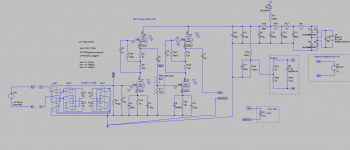
Some notes:
All resistors are metal film 0.25W, except
R10, R8 - 10W
R19,R18,R17 - 5W
R20,R21 - are tube heaters.
All capacitors must be at least 400V except C5,C9,C6,C14.
C3,C2,C4,C7,C9,C14,C12 - film caps
C16 - I use PP motor run capacitor to bypass reservoir electrolitics.
PSU for heaters is external. It can be any type, 12V, >=2A. I use switching mode one.
Feeding heaters from same transformer as H+ pollutes H+ with buzz.
Placing a second transformer for heaters inside preamp box radiates buzz as well.
So I decided to make it completely external and remote.
Turn On procedure: turn heaters on first, wait 10 sec, turn B+ on.
Turn Off procedure: turn B+ off, wait until D5 becomes dull, turn heaters off.
WARNING!
RESERVOIR CAPACITORS KEEP VERY HIGH VOLTAGE FOR DOSENS OF MINUTES AFTER THE DEVICE IS TURNED OFF.
C3, C4, C2 AND C5 CAPACITORS CAN KEEP HIGH VOLTAGE FOR MANY HOURS.
DO NOT TOUCH PARTS UNLESS YOU KNOW WHAT YOU ARE DOING!
Elevation voltage 100V goes into the external heaters PSU.
TREAT HEATERS PSU, ITS CABLE AND CONNECTOR AS HIGH VOLTAGE - IT DOES CARRY HIGH VOLTAGE!
LED D5 lits when high voltage is in reservoir capacitors.
DO NOT TOUCH HEATERS CONNECTOR UNTIL THIS LED IS COMPLETELY OFF!
The amplifier is designed specifically for ribbon microphones.
It has very high input impedance - 1M Ohm (set by R6).
This allows to decrease damping of the ribbon in microphone.
But dynamic mics work well with it too.
Last edited:
These are wonderful notes. I sure as hell have learned a lot here.
I also feel that this has been a true first for documentation on a proper DIY ribbon preamp. Small signal amplification is a whole different world of knowledge. Once I begin making one for my self, I would like to compile the notes you made into some sort of compilation pdf
I also feel that this has been a true first for documentation on a proper DIY ribbon preamp. Small signal amplification is a whole different world of knowledge. Once I begin making one for my self, I would like to compile the notes you made into some sort of compilation pdf
- Status
- This old topic is closed. If you want to reopen this topic, contact a moderator using the "Report Post" button.
- Home
- Amplifiers
- Tubes / Valves
- Ribbon Microphone Preamp