>Key word to notice in the above is "MAGNETIC".
Chris, key word was varying magnetic field.
>Really there is only one "EM field"
Exactly.
>The E field is very easy to shield, the M is not so easy.
If M field is not easy to shield, especially using copper, then it should not impact signal cables. It should go through them without generating too much buzz. Right?
Here it is how it sounds.
And this buzz does not disappear when I close the chassis with aluminum cover, if I put aluminium sheet between PSU and signal circuit.
Also there are short "pf pf pf" sounds. where these from?
This sounds like environmental noise, not power supply hum. There is no 50Hz component (I assume you have 50Hz power but there is also no 60hz. I measured it using FFT.)
I'd try turning off stuff in the house, the computer, the lights, TV sets,.... The buzz is a bit broad spectrum. Try with no microphone cable, juist theat 200R resister.
I have a flourecent desk lamp that make noise just like this and I have to UNPLUG it to stop the noise, the off switch does not disconnect the transformer from the AC mains. Be warded that most modern electronics is like this and has to be unplugged to be fully "off". Sounds like noise from switch mode power supplies.
The "puff-puff" type noise could be a "beat" frequency from two sources that are only about one Hz off, say a 50 KHz and a 49.999 KHz power supply.
Removing the mic cable will help tell you where the noise is being picked up.
One thing for sure the noise is being effected be the volume control, so it is getting into the amp ahead" of the volume control pot, not after it.
That is very interesting for sure. The kicker for me is the pf-pf sound. regular and not regular. Flyback style?
I feel like it could be a mis-read resistor value. On another amp, I had a cathode resistor value misread by a whole k. Produced similar noise but alot worse. No pf pf sound though.
I feel like it could be a mis-read resistor value. On another amp, I had a cathode resistor value misread by a whole k. Produced similar noise but alot worse. No pf pf sound though.
This sounds like environmental noise, not power supply hum. There is no 50Hz component (I assume you have 50Hz power but there is also no 60hz. I measured it using FFT.) ....
mains is 60Hz in Canada.
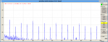
I've analyzed buzz fragment of the file - 60Hz and its harmonics are sticking out significantly. Especially 60 and 300Hz.
Attachments
Last edited:
I read this thread DIYHiFi.org • View topic - Power transformer shielding(external).
They are talking about 1/4" thick aluminum shielding. Wow.
I suggest a better way would be to separate PSU and preamp.
Also, for rectification I use not separate diodes but rectifier KBU8G.
Can it cause buzz?Why the buzz is not smoothed by caps?
They are talking about 1/4" thick aluminum shielding. Wow.
I suggest a better way would be to separate PSU and preamp.
Also, for rectification I use not separate diodes but rectifier KBU8G.
Can it cause buzz?Why the buzz is not smoothed by caps?
PSU caps smooth voltage. They don't smooth current; for that you need a big choke.mm7 said:Why the buzz is not smoothed by caps?
mains is 60Hz in Canada.
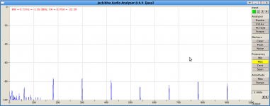
I've analyzed buzz fragment of the file - 60Hz and its harmonics are sticking out significantly. Especially 60 and 300Hz.
Is it really right at 60Hz? Look more like close to 60Hz to me.
One other thing is that rectified 60Hz is 120Hz. So if there is not enough filtering you get 120 not 60. The diodes have the effect of a frequency doubler.
Still sounds like environmental noise to me, coming from outside your amp. We will see if the screen shot of my spectrum is attached properly. If it is then yes there is something near 120Hz. The blue cursoe is on it ad its harmonic but there is loads of other "trash" on the screen to. If if this is mains AC leaking in it might NOT be from your power supply.
Because the buzz gets amplified when you turn the volume, I'd say that means the noise gets in prior to the steppe attenuator.
Sorry for missing you were in Canada. I Can't see the little flag as I type
Attachments
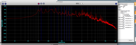
>Is it really right at 60Hz? Look more like close to 60Hz to me.
Yes it is. It may look a little bit off on the chart because of log scale and FFT is a little bit rough on 60Hz. But it is 60Hz and its harmonics - 120, 300 etc ...
I read about ringing in PSU, and how to fight it using snubbers.
Thinking to put snubbers on bridges.
Why RC snubber should be put across each diode in bridge?
Will be just one on AC side and one on DC side enough? Let say 50nF and 50R each?
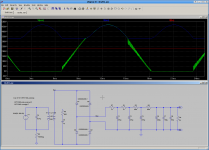
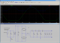
Snubber removes ringing, but signal shape on secondary is still has sharp square angles. This causes FFT with harmonics.
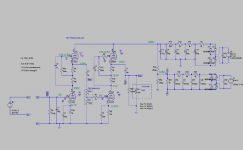
Here are pictures of simulations with and without snubber.
What signal shape should be achieved on secondary?:
a) Without ringing;
b) Without ringing and smooth, without sharp edges;
c) close to sinusoidal, with some harmonics;
d) ideally sinusoidal.
"Signal" here is mains 60Hz.
Why the snubber did not help in my case? preamp still buzzes same way.
Attachments
Last edited:
>Why the snubber did not help in my case? preamp still buzzes same way.
I think I know. With snubber C 0.1uF supression of ringing is insufficient.
I had to increase it to 1-5uF in simulation.
In reality I've got caps to make it 3uF and tried. My 500R 0.5W smoked after couple of seconds. I had to stop it.
In model simulation current through the snubber R shows amplitude -0.350mA - +0.350mA AC. That is 0.7A AC or about 0.5A DC. From equasion P=R*I^2, power of a resistor has to be 123W (!).
With C 1uF power of R needs to be 23W.
The more C is the closer voltage and current on secondary to sinusoid. But price for it - a higher current on R.
Still have a question. Will it only suppressing of ringing oscillations be sufficient, or sharp edges on signal shape should also be smoothed, or even further, signal shape should be sinusoidal? What shape is more important - voltage or current?
Again, my understanding of EMI in my case is following. Rectifier diodes abruptly stop current that causes oscillations of voltage and current. These oscillations come back to secondary of the toroid transformer and cause EM radiation that is picked up by preamp.
Is my understanding correct?
Snubber removes ringing, but signal shape on secondary is still has sharp square angles. This causes FFT with harmonics.
Here are pictures of simulations with and without snubber.
I think you need a better transformer model. You are using an ideal transformer. As a first cut place a resister equal to the DRC of the secondary in series with the secondary. You might try to put 1/2 the DCR on each side but I doubt that will matter.
This more accurate model I think will give better results.
Next you add leakage inductance to the model but you'd have to measure you transformer to know what that is.
One cheap way to remove those switching spikes is to place a small cap in parallel with each diode about 10nF is right.
Also you will notice how adding the transformer DRC into the spice model helps. You can add resisters to the real circuit too. See "Rlim1" and Rlim2" on the fourth example on this page
The Valve Wizard
Lastly chokes work very well to control power supply hash. The value is not important. Try about a 4H to 9H choke in place of one of the power supply filter resisters. Something like this Choke 40mA 4H Fender Deluxe / Champ 22707 MADE IN USA
To see how effective it will be estimat the frequency of the spikes, then look at the reactance of a 4H at that freq.
To remove power supply noise you may need to try an "all of the above" approach. But I still think the buz in environmental
One more experiment. Do you have a variac? change the input AC voltage and see if the noise amplitude tracks the input voltage. You will need to run the heaters off a separate supply.
I normally breadboard amplifiers using my high voltage bench supply. it is worth building one of these so that later you have a known good B+ supply and don't have to debug and amp and the PS at the same time.
Chris, thanks for advises. It looks like I've found the cause of buzz.
Yesterday I just randomly placed 0.1u cap across top resistor of heater elevator voltage divider. Buzz decreased by 30-40dB! It become less than -80dB but still audible.
Today I started searching/reading about elevators and found that quite a big cap (20-100uF) should be placed across a bottom resistor.
Look pic 3 at http://forum.metroamp.com/download/file.php?id=5062.
Also I use 2MR resistors in divider to reduce a current. It looks it too high. I'll try with two 100kR and some cap across the bottom one.
Though I still do not understand how it works. My heater supply is DC, not regulated but very well filtered with three RC of 10000uF caps. How buzz appears?
Does it come from a ripple of heater supply into H+? or vice versa?
Or because heater circuit is floating, connected to ground only via the bottom R of elevator, it picks up RF/EMI and passess it somehow emitting/consuming electrons to cathode?
I suspect the any noise transfore from heater circuit to signal path was happening otside of the tubes because you hade the heater elevated well abouve ground. I'd guess the transfer was very close to the tube socket where the wires are just millimeters apart
Look at this photo of an amplifier I built. guts.jpg
The preamp tube is the one in the aluminum tube shield. You can see the copper tape I used to hold the heater wires down to the chassis, and maybe provide a little electrical shielding too. But mostly notice how the heater wires reach UP to the tube socks and the signal wires reach DOWN into in the socket. (same idea in the center tube too, see the heater wires reaching up and comming from a different angle than the other wires.) The two wires that connect the grid are coaxial (red and blue) the last bit of the shield is under the black shrink wrap. The layout and exact routing of the wires is important. In the preamp all signal wire run on a vertical plane the heater is on a horizontal plane. They can't couple that way. See that I've left a good deal of empty space around all the preamp components but allow crowding in the power section. All the voltage gain is in the preamp and that is the part most sensitive to noise.
I'm a fan of using turret boards. I think they are the best compromise between PCBs and point to point. Turret boards are also very serviceable later.
This amp is a copy of a 1950's Fender design but I used modern grounding and assembly practice and the amp is very quiet compared to a real 50's vintage Fender Champ.
Fender got a few things right, See the power transformer is as far rom the preamp tube as allowed by this small size chassis and the audio transformer and choke are on the side of the chassis facing the speaker. The chromed steel chassis offers some magnetic shielding also.
Next subject...
If you think about how a real-world transformer works you see it differs from the simple Spice model. Take a look at the link below. It shows how to create a better model. You need to use something like this to model problems like noise. Transformers - LTwiki-Wiki for LTspice
Your cap on the voltage divider provides a short circuit for AC voltage to ground.
As you work off the remaining noise you might even find out why most people who use DC heaters also use a regulator. Those regulators are great for suppressing transients and ripple. The LM317 regulator is also smaller and cheaper than a big filter cap
There is another small effect: Do you have a 'scope? Look at the heater secondary AC waveform. Usually it is not a perfect sine wave. That is because the current in the primary is not constant and that is because the current on the B+ secondary is anything but constant. It is zero when diodes don't conduct and much higher when they do. Some of this gets reflected on the 6.3V secondary. This effect is much larger on power amps then a preamp
Oh wow, who would of thought. A good lesson.
But I too would like to know more on the buzzing derived from elevation
I don't think the buzz was the result of elevation but of there being no good AC path to ground.
We also don't know yet how those switching spike were being coupled to the DC heater supply. My guess after looking at the assembly photos is that this is a very "tight" layout with components and their leads all placed close together.
Remember that if you want a wire to pick up stay signals from it's environment the best way to make that happen is to give it a high impedance from ground and use lots of wire. A heater circuit tied to ground only with a 1M resistor is the very definition of that. Adding that cap gave it a nearly zero impedance to ground.
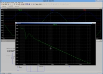
I've changed elevator resistors to 100K and bypassed the bottom one with C 220uF.
Buzz reduced dramatically.
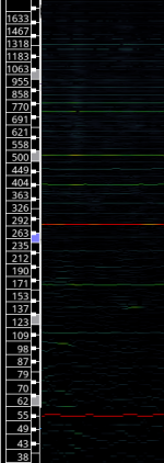
But there is still some dry buzz made of 180Hz and higher harmonics of 60Hz.
Here is pic taken with volume at 75%.
PS/ When I turn off power, the preamp still works on reservoire caps energy for couple of seconds. No buzz just some hiss.
Buzz reduced dramatically.
But there is still some dry buzz made of 180Hz and higher harmonics of 60Hz.
Here is pic taken with volume at 75%.
PS/ When I turn off power, the preamp still works on reservoire caps energy for couple of seconds. No buzz just some hiss.
Attachments
Last edited:
- Status
- This old topic is closed. If you want to reopen this topic, contact a moderator using the "Report Post" button.
- Home
- Amplifiers
- Tubes / Valves
- Ribbon Microphone Preamp