#1 XLR Pin-4 is XLR ground, shown as rectangle here Sound System Interconnection on Figure 1b. So it can be soldered with pin-1?
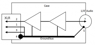
Pin-2 is hot signal. However Pin-3 directly goes to Signal Ground because the preamp is not balanced. The Star Point in my case is XLR Pin-4. So Pin-3 is soldered to it. Is it correct?
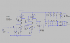
Currently, in schematic it looks like on the picture attached. Triangles are tube cascades.
Another thing, mains earth is bolted far away from XLR where Start Point is.
mains earth is bolted on back surface nearby power cord plug.
Pin-2 is hot signal. However Pin-3 directly goes to Signal Ground because the preamp is not balanced. The Star Point in my case is XLR Pin-4. So Pin-3 is soldered to it. Is it correct?
Currently, in schematic it looks like on the picture attached. Triangles are tube cascades.
Another thing, mains earth is bolted far away from XLR where Start Point is.
mains earth is bolted on back surface nearby power cord plug.
Attachments
Ian thanks.
But in this article you described grounding of a balanced preamp with input and output transformers.
Mine has no transformers. I removed the input transformer because mic signal is strong enough.
What to do in case of unbalanced preamp without transformers?
Is it really "the must" to have mains earth as a star point?
I read somewhere that star point should be as close to input connector as possible. So I decided to place it on XLR ground pin. Automatically it happens that shortest way for pin-1 and V0 (pin-3) is just to solder them all together to the ground pin. Is this way wrong?
Very confusing. Go back to basics and keep out of the box as much as possible.
XLR Pin1 Ground, pin 2 +ve input, pin 3 -ve input pin 4 use it as a ground if you wish, (there is no need).
The star point should be at the output stage , why? because all of the current is drawn at the output, not the input!
XLR Pin1 Ground, pin 2 +ve input, pin 3 -ve input pin 4 use it as a ground if you wish, (there is no need).
The star point should be at the output stage , why? because all of the current is drawn at the output, not the input!
#1 XLR Pin-4 is XLR ground, shown as rectangle here Sound System Interconnection on Figure 1b. So it can be soldered with pin-1?
Pin-2 is hot signal. However Pin-3 directly goes to Signal Ground because the preamp is not balanced. The Star Point in my case is XLR Pin-4. So Pin-3 is soldered to it. Is it correct?
Currently, in schematic it looks like on the picture attached. Triangles are tube cascades.
Another thing, mains earth is bolted far away from XLR where Start Point is.
mains earth is bolted on back surface nearby power cord plug.
If that is what you built then it is working about like I'd expect it so. Such a design has zero common mode rejections and will amplify any and all hum it picks up.
On top of this you have a ground loop too. The ground bus and chassis seem to be wired in parallel. There should be at most ONE connection from signal to chassis ground. Some argue for zero, some for one. But two is always the wrong answer.
You need a balanced or differential input. What your amp needs to amplify is the difference BETWEEN pins 2 and 3 not the level of on of them above ground.
Also, importantly, what is the input impedance of this amplifier? I'm betting is is very high. The also is an invitation to hum.
You are best off getting an input transformer. There is a reason "everyone" uses them.
Isolation of the output 1/4" connector does nothing. Buzz is same.
@ ChrisA
I do not understand what is wrong if 3 is on the ground. There will be still same difference between 2 and 3.
@ ChrisA
What your amp needs to amplify is the difference BETWEEN pins 2 and 3 not the level of on of them above ground.
I do not understand what is wrong if 3 is on the ground. There will be still same difference between 2 and 3.
Last edited:
Isolation of the output 1/4" connector does nothing. Buzz is same.
@ ChrisA
I do not understand what is wrong if 3 is on the ground. There will be still same difference between 2 and 3.
Isolation of the ground is a minor thing compared to this. At present you have other problems that mask this small effect.
To understand why you don't ground pin 2 or 3, first think about WHY people use balanced signals. Let's say your microphone and the microphone cable are inside an electric field. They are, you can't escape it because the power grid is "everywhere". Then BOTH the pin 2 and pin 3 will raise and lower their voltage. They act like one plate of a capacitor. Their voltage moves up and down together. We call this "common mode" noise because it is common to both conductors.
Let n = noise picked up from the environment and s be the audio signal.
In a truely balanced system, if you measure the difference between the two wires you do not see this 60Hz (or 50Hz) noise. Pin two has n+s/2 and pin three has n-s/2 do the difference is s.
Now in your design you have fixed one pin at zero volts. The other pin has n+s on it. The difference is n+s.
OK what the above ignores is that the microphone has about 200 ohms of impedance and all the wires have some resistance. So grounding the pin 3 has the effect of pulling pin 2 to ground through the the mic's internal resistance. Let others comment if I am right but I think this has the effect of tossing out away half the signal.
Next problem is the input impedance of the amplifier? This the "load" the microphone sees. You modle it as if the mic was an AC generator and the amp a resistor. If it is high like the grid on a tube then the load on the mic then there is very little load on the mic and the voltage to current ratio is high. I cable running into such an amp acts like an antenna.
An input transformer words because it makes absolutely sure the two input pins 2 and 3 have identical current and voltage. The transformer can not pass any common mode noise. it is a near perfect blocker (except for inter winding capacitance.) Not only does it block common mode noise it provides near noiseless voltage gain (8 to 10 x) and importantly it matches the low mic impedance to the high tube impedance.
So your amp is amplifying all the noise and half the signal while a transformer based based amp sends 16 times the signal and almost none of the noise to the first tube.
Electric guitar players are used the kind of amp you have and just put up with the noise, they play loud enough to cover it up.
Chris, I understand benefits of balanced topology. But there are tons of all kinds of single ended topology preamps. They all work. May be not that excellent as balanced ones, but well enough. May be mine next project will be a balanced one.
Regarding half signal, I think, it is wrong. Moving 0 from the middle to the bottom does not reduce whole amplitude, it is just changing a reference. I think.
I'd agree with s+n, but "the thing" is buzzing even without a cable. I just plug 100 Ohm resistor and it buzzes.
Currently impedance is set to 1MOhm. Probably it is a good idea to reduce it to 100K or 50K.
Ribbon mic itself has transformer inside. Its ratio is 1:37. It is just about enough. Initially I wanted to put 1:5/10/20 input transformer with switching between these ratios, but Per Lundahl kindly advised against that - 1:20 will bee too much. It will impact LF and HF. He proposed another transformer with ratios 1:5 and 1:10 max.
But I tried without an input transformer, signal is strong enough so I've decided to go without it. I'll put it there if it really will help to cancel noises. Hm, I never thought about a transformer in this dimension.
Although a transformer adds another distortions, but if it will cancel noises, it would make sense to use it.
The buzz now is too strong even for a guitar amp.")
Regarding half signal, I think, it is wrong. Moving 0 from the middle to the bottom does not reduce whole amplitude, it is just changing a reference. I think.
I'd agree with s+n, but "the thing" is buzzing even without a cable. I just plug 100 Ohm resistor and it buzzes.
Currently impedance is set to 1MOhm. Probably it is a good idea to reduce it to 100K or 50K.
Ribbon mic itself has transformer inside. Its ratio is 1:37. It is just about enough. Initially I wanted to put 1:5/10/20 input transformer with switching between these ratios, but Per Lundahl kindly advised against that - 1:20 will bee too much. It will impact LF and HF. He proposed another transformer with ratios 1:5 and 1:10 max.
But I tried without an input transformer, signal is strong enough so I've decided to go without it. I'll put it there if it really will help to cancel noises. Hm, I never thought about a transformer in this dimension.
Although a transformer adds another distortions, but if it will cancel noises, it would make sense to use it.
The buzz now is too strong even for a guitar amp.
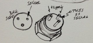
I think you may have 1 & 3 pins flipped. When I was making my ribbon mic, I ran into the same buz with low signal issue. Turns out I was over complicating my own schematic and flipped the socket connections 1 and 3 around.
Actually... I confused the 1,2,3 thing here. just check out the attachment
Actually... I confused the 1,2,3 thing here. just check out the attachment
Attachments
Last edited:
Woodrough, pins are marked with little numbers on my XLR. No way to flip.
Also it buzzes even without a cable and mic attached. I plug resistor 100 Ohm it still buzzes.
However when it is open, nothing in XLR, it buzzes very very loud.
I am guessing now what would be a source for this buzz, PSU via wires or EMI/RF via air?
Woodrough, have you built this preamp? Did you use an input transformer? If yes, which.
Do you have buzz issue?
Shamefully no, I haven't built the preamp yet. Ive been working/putzing with designing my ribbon mic this whole past time. (Which has been a success). When first piecing together the mic for the first time, I had some micro confusion about shield and common being confused with the signal / hot. The result sounded very much like what you were having. Until you said that when you unplugged the device...
Which brings me to another project I worked on that had a similar area of buzz confusion. I made a D3a headphone amp. One stage only, not a lot to screw up with. I first turned it on and got some impressive hum going on. Very and barely audible signal coming across when I cranked the potentiometer. Plugged and unplugged, moved the power supply around, yelled at it, stared at the grounding schemes, rewired outputs from balanced to unbalanced... etc loosing my mind.
For some ungodly reason, I unplugged both tubes waved them around, traded / switched them around and re-seated them back in there sockets. Turned it on, same thing... turned it off, wiggled them around in their sockets some more, turned it on... and the whole amp was working as if nothing wrong happened in the first place. I dont know if it was a learning experience for me, but maybe you might have a similar issue.
such loud buzzing cant possibly attributed to environment EMI/RF effects on a properly hooked up amp.
Replaced regular wire from XLR to grid with shielded one. Much less noise. But still some buzz is bleeding.
Aluminum shield wall between PSU and amp makes no difference.
It looks like EMI comes from mains transformer. It is toroidal and should not radiate too much EMI. But it does. And it penetrates through aluminium shielding. Should use steel shielding between compartments?
Thinking now to separate preamp and PSU.
Replaced regular wire from XLR to grid with shielded one. Much less noise. But still some buzz is bleeding.
Aluminum shield wall between PSU and amp makes no difference.
It looks like EMI comes from mains transformer. It is toroidal and should not radiate too much EMI. But it does. And it penetrates through aluminium shielding. Should use steel shielding between compartments?
Thinking now to separate preamp and PSU.
Aluminum does not do anything to a magnetic field. If noly helps with electric fields. Some people use old steel cans, maybe from soup, tuna or canned fruit. Two layers, one inside the other works even better. Just make sure to NOT create a "shorted turn" that is where to place a bolt through the toroid that makes a conductive path all around. I think Antek sells nice pre-made cans and mounting hardware.
http://www.antekinc.com/pdf/CA-xxx.pdf
But as I said you can a DIY can
The way to visualize a magnetic shield is to think about "giveing the magnetic field lines a much "better" path to follow. So you need a steel loop. A closed steel can does that. The very high end input transformers use MuMetal cans some times double layers of mumetal and the cans are sealed up with only a small hole for the wires. I double you need to go that far.
I use shielded wire for every signal that feeds a high impedance. Certainly anything that connects to a tube's grid. Ground the shield at only one end.
If you have "grid stoppers" installed, those are resisters in series with the grid. use a very short lead and solder the resister directly to the tube socket. 10K to 68K is about the right value. They form a low pass filter when combined with the tube's Miller capacitance and keep hum and RF out of the tube. Some of the hum and buzz is caused by RF spikes spaced at 50 or 60 hz or multiple there of. the stopper will help.
You found the shield good at keeping noise OUT. They also work to keep noise INSIDE a wire too. Cut up old video cables or old RCA hookup wire and get all the wire you need. But I buy RG178 coax cable, 20 feet lasts a LONG time
Other places that radiate hum are the wires going to and from the power transformer, make sure they are twisted and make sure the cross any signal wires are right angles.
Eventually you need this to have a noise floor at -80dB or better. You will need to use every trick you've hear of.
Last edited:
>Aluminum does not do anything to a magnetic field.
Copper is also non-magnetic, but copper-shielded wire works.
Magnetic fields, if changing, create current in any conductor they go through.
Same way they create noise current in copper signal wires.
Wires, both B+ and filaments, from PSU are twisted and have (should have) very smooth DC.
I tested with short disconnecting filament wires from PSU - it does not reduce buzz. So it is not filament ripple then.
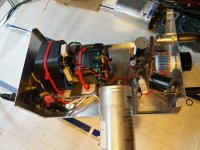
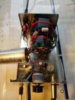
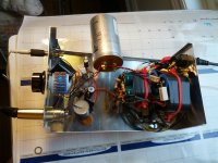
My toroid is covered with a thin steel can. The can is attached to chassis and does not touch central bolt.
This is transformer Toroid Transformer T30L 45W 0-120-200-220-260-280-320V/50mA 0-5-6.3V/1.5A x2 18V/1A_Toroidal Core_Power Transformer_Analog Metric - DIY Audio Kit
I use my ribbon mic as a device to search a buzz source.
Buzz increases when I bring my ribbon mic close to transformer, to 3 inch distance, or to filter capacitors too.
I could shied all signal wires but there also is big attenuator that also should be covered, and resistors and capacitors. All them can pickup.
So, instead of shielding each part and little wire, I preferred to shied the whole circuit.
But again, the thin aluminium wall between PSU and preamp does not work. Closing the chassis does not help.
This puzzles me.
I read that only thick steel or mu-metal can save from a low frequency EMI.
Would it be a good idea to place whole signal circuit into an electrical steel box?
And tubes to cover with steel mesh cups?
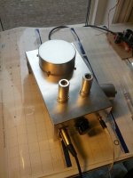
here are pics. Big Vishay motor run cap is sticking out temporarily to improve visibility for pics.
Copper is also non-magnetic, but copper-shielded wire works.
Magnetic fields, if changing, create current in any conductor they go through.
Same way they create noise current in copper signal wires.
Wires, both B+ and filaments, from PSU are twisted and have (should have) very smooth DC.
I tested with short disconnecting filament wires from PSU - it does not reduce buzz. So it is not filament ripple then.
My toroid is covered with a thin steel can. The can is attached to chassis and does not touch central bolt.
This is transformer Toroid Transformer T30L 45W 0-120-200-220-260-280-320V/50mA 0-5-6.3V/1.5A x2 18V/1A_Toroidal Core_Power Transformer_Analog Metric - DIY Audio Kit
I use my ribbon mic as a device to search a buzz source.
Buzz increases when I bring my ribbon mic close to transformer, to 3 inch distance, or to filter capacitors too.
I could shied all signal wires but there also is big attenuator that also should be covered, and resistors and capacitors. All them can pickup.
So, instead of shielding each part and little wire, I preferred to shied the whole circuit.
But again, the thin aluminium wall between PSU and preamp does not work. Closing the chassis does not help.
This puzzles me.
I read that only thick steel or mu-metal can save from a low frequency EMI.
Would it be a good idea to place whole signal circuit into an electrical steel box?
And tubes to cover with steel mesh cups?
here are pics. Big Vishay motor run cap is sticking out temporarily to improve visibility for pics.
Attachments
Last edited:
...
I read that only thick steel or mu-metal can save from a low frequency EMI.
Would it be a good idea to place whole signal circuit into an electrical steel box?
And tubes to cover with steel mesh cups?
here are pics. Big Vishay motor run cap is sticking out temporarily to improve visibility for pics.
Above you argued that copper can act as a magnetic shield. Read this to get the correct answer Electromagnetic shielding - Wikipedia, the free encyclopedia
One way to improve power supply hum is to remove the power supply to a separate chassis and use a cable. The transformer and all the AC wire is 3 feet away from the amplifier. You have to think about safety when you make a high voltage cable. What if your cat or a small child tugs on the cable?
You also need some filtering in the amp chassis to remove whatever the cable picked up from the environment.
>Above you argued that copper can act as a magnetic shield.
I did not argue. It is a fact - shielding in most of the audio cables I saw was copper. I used 2" piece of audio cable to replace a wire from input XLR to tube grid. It helped.
In your link it is stated
But transformer's buzz is 60Hz. That is why it is very hard to reflect it. It penetrates through nonferrous shielding. It changes too slow to create significant eddy currents, I think.
Thus only two solutions:
A - put signal circuity into a thick steel box. Better if mu-metal, but it is too expensive.
B - to separate chassis.
I'm thinking to try A first.
Did anybody try this? How thick a steel should be?
I did not argue. It is a fact - shielding in most of the audio cables I saw was copper. I used 2" piece of audio cable to replace a wire from input XLR to tube grid. It helped.
In your link it is stated
to protect from HF EMI a shielding does not need to be ferromagnetic.Similarly, varying magnetic fields generate eddy currents that act to cancel the applied magnetic field. (The conductor does not respond to static magnetic fields unless the conductor is moving relative to the magnetic field.) The result is that electromagnetic radiation is reflected from the surface of the conductor: internal fields stay inside, and external fields stay outside.
But transformer's buzz is 60Hz. That is why it is very hard to reflect it. It penetrates through nonferrous shielding. It changes too slow to create significant eddy currents, I think.
Thus only two solutions:
A - put signal circuity into a thick steel box. Better if mu-metal, but it is too expensive.
B - to separate chassis.
I'm thinking to try A first.
Did anybody try this? How thick a steel should be?
>Above you argued that copper can act as a magnetic shield.
I did not argue. It is a fact - shielding in most of the audio cables I saw was copper....
Key word to notice in the above is "MAGNETIC".
The shielding we see in cables is for ELECTRIC fields.
Yes to two are coupled one is a reciprocal of the other but if we are talking about transformers the coupling is nearly 100% magnetic. If you look at the better quality audio transformers you find faraday shields between the layers of coils. These are typically sheets of thin copper foil that are all grounded. If these worked to block a magnetic field then the transformers would not work.
As a practical matter do you need any magnetic shielding in this amp? Likely not. It is an unlikely coupling method unless you happen to have two transformers near each other.
Remember that magnetic fields are created by current and electric fields by voltage. Really there is only one "EM field" but like vectors we can break them down to orthogonal components or E and M fields. The E field is very easy to shield, the M is not so easy.
>Key word to notice in the above is "MAGNETIC".
Chris, key word was varying magnetic field.
>Really there is only one "EM field"
Exactly.
>The E field is very easy to shield, the M is not so easy.
If M field is not easy to shield, especially using copper, then it should not impact signal cables. It should go through them without generating too much buzz. Right?
Here it is how it sounds.
And this buzz does not disappear when I close the chassis with aluminum cover, if I put aluminium sheet between PSU and signal circuit.
Also there are short "pf pf pf" sounds. where these from?
Attachments
Last edited:
>Key word to notice in the above is "MAGNETIC".
Chris, key word was varying magnetic field.
>Really there is only one "EM field"
Exactly.
>The E field is very easy to shield, the M is not so easy.
If M field is not easy to shield, especially using copper, then it should not impact signal cables. It should go through them without generating too much buzz. Right?
How do transformers that have an electrostatic shield around each coil work? Clearly the primary and secondary are magnetically coupled even if each is surrounded by a grounded shield.
I don't think this is the problem. I'm betting it will turn out to be the design of the ground system. Or maybe even bad part or an error in construction, reading a resistor code wrong, I've done that a few times.
I had to practically disassemble an amp once to find a problem. rebuilt it stage by stage, testing after each step. You will find it eventually.
Last edited:
- Status
- This old topic is closed. If you want to reopen this topic, contact a moderator using the "Report Post" button.
- Home
- Amplifiers
- Tubes / Valves
- Ribbon Microphone Preamp