Here is article on Mains DC Stopper. Mains DC and Transformers
Rod Elliot mentions:
I am not sure how "big" transformer is required for our preamp. Dissipation on voltage source V2 shows 4W. heaters also should be added. It looks like it will go above 500VA.
Am I right? So the Mains DC Stopper may be helpful for a toroid.
Rod Elliot mentions:
It's also worth noting that DC is usually not a problem with toroidal transformers of 300VA or less. Their primary resistance is usually high enough that any DC will have little effect. With larger transformers (500VA and above), the DC resistance is usually so low that even a very small offset will cause mechanical noise due to saturation.
I am not sure how "big" transformer is required for our preamp. Dissipation on voltage source V2 shows 4W. heaters also should be added. It looks like it will go above 500VA.
Am I right? So the Mains DC Stopper may be helpful for a toroid.
Oh yes, I see.
Regarding a toroid trans, what mains power do you have? 2 or 3 phase?
I know in Russia it is 3 phases by 220V 120 degree shift (regular residential receptacles use 1 phase), in US and Canada it is 2 phases by 120V 180 dgr shift. It looks like toroids should work without problems in North America, but may be problems in Russia because of DC bias. What type of power do you have?
Here in the UK we have three phase mains with a single phase supply to houses.
Cheers
Ian
Thanks IanHere in the UK we have three phase mains with a single phase supply to houses.
if you do not have issues with toroids it means that they should be OK for preamp. What toroid VA would be sufficient for the preamp? What do you think about R-core?
I always feel inconclusive with the EI vs Toroid debate. It looks like the emi field of a toroid is a small fraction (1/8) of a EI core. So the question is, what is the minimum acceptable distance I should keep the input transformer from? *(with either version)?
I envision putting this in an all in one multi story enclosure.
You figure this out by experiment. Put AC and a dummy load on the power transformer and a millivolt or microvolt AC meter in the input transformers and rotes and move around the transformer until you get a minimum. You may need to place each transformer inside its own steel box. Then each steel box mounts inside diagonal corners of the aluminum chassis. Do this experiment first before any other layout starts.
You might find a torroid PT is the best Don't worry about DC component on the AC, this preamp is using only a very tiny amount of current and the PT will likely be 10X over size.
Thanks Ian
if you do not have issues with toroids it means that they should be OK for preamp. What toroid VA would be sufficient for the preamp? What do you think about R-core?
You have HT of 300V at about 20mA which is 6 watts. You have to make an allowance for the method of rectification so to be very safe let's double this to 12 VA. The heaters are 6.3V at less than 1 amp for another 6 VA. Assume dc heaters so double this as well to 12VA so you have 24 VA consumption at most. A 25VA transformer will be ample.
I don't know of any 25VA off the shelf transformers with 6.3 and 240V secondaries. There are some 50VA ones though. Antek make a range of them at very reasonable prices. For example:
Antek - AS-05T240
Cheers
Ian
Antek is great!
One fear I have though when looking at their transformers, despite their convenient 6.3v secondaries, is the fact that I want to use DC heaters not AC. Would you recommend voltage doubling? Looks like the AS-05T240 should have enough current abilities to run just two tube heaters in voltage double mode?
And if so, full wave voltage doubling:
Vdc = (Vac x 2.8) - 2V
15.64v regulating to 12.6 is safe? or is regulating down to 6.3v safer? (if a LT1085 or other is used to regulate)
Here is a nice little transformer.
http://www.hammondmfg.com/pdf/EDB370X.pdf
You could use the 5v tap on this one and double it.
http://www.hammondmfg.com/pdf/EDB370X.pdf
You could use the 5v tap on this one and double it.
Here is a nice little transformer.
http://www.hammondmfg.com/pdf/EDB370X.pdf
You could use the 5v tap on this one and double it.
Mel thanks, but we need 50VA 300-320V B+, 12-14V for heaters, and low external field. Unfortunately our Hammond does not make such toroids.
Antek is great!
One fear I have though when looking at their transformers, despite their convenient 6.3v secondaries, is the fact that I want to use DC heaters not AC. Would you recommend voltage doubling? Looks like the AS-05T240 should have enough current abilities to run just two tube heaters in voltage double mode?
And if so, full wave voltage doubling:
Vdc = (Vac x 2.8) - 2V
15.64v regulating to 12.6 is safe? or is regulating down to 6.3v safer? (if a LT1085 or other is used to regulate)
The model, I mentioned has two separate 6.3V windings so you can connect them in series for 12.6VAC and regulate down from that.
You need less than 1 amp heater current and this transformer is rated at 2 amps. This means that inpractice the diode voltage drop will be less than the 2 volts you have assumed. Also if you use a low drop out regulator like the LM2940 you can regulate to 12 volts from as little as 14 volts.
Cheers
Ian
I've contacted Per Lundahl again regarding use of LL1636 input transformer with switchable ratios 1:5, 1:10 and 1:20.
Hi recommends to use LL1935 (1:5 or 1:10) as a best choice with source impedance up to 300 Ohm. 1:20 is too optimistic, low and high end signal will be lost, he said.
Most likely I will go with LL1935.
Hi recommends to use LL1935 (1:5 or 1:10) as a best choice with source impedance up to 300 Ohm. 1:20 is too optimistic, low and high end signal will be lost, he said.
Most likely I will go with LL1935.
I've made a pre-build on a cardboard sheet. It works even without an input transformer - I can hear all sounds from my ribbon mic in earphones plugged into output.
Though it buzzes because there is no RF shielding currently, I believe it will not buzz after final build in an aluminum project box.
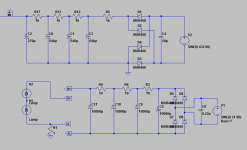
Also, I use a simple RC (four caps, 150,270,270,150uF, with three 1KR between them) filter power supply, with DC heaters. Not regulated.
Simulations show no ripple.
I hope all the buzz is from RF over air, not from DC over chains.
Though it buzzes because there is no RF shielding currently, I believe it will not buzz after final build in an aluminum project box.
Also, I use a simple RC (four caps, 150,270,270,150uF, with three 1KR between them) filter power supply, with DC heaters. Not regulated.
Simulations show no ripple.
I hope all the buzz is from RF over air, not from DC over chains.
Last edited:
I do not hear hiss. May be currently buzz is too loud.
Do you hear hiss when mic is plugged?
When nothing is plugged mine preamp makes all kinds of noises.
But mine is on cardboard, open to RF. I've got aluminium project box and going to assemble the thing during this week. Will see. Mean - hear.
To all:
Regarding PS RC filter. I've found that different caps can colorate or even spoil sound.
High End Audio - Electrolytic capacitors
Currently I use regular (not audio grade) caps. Nichicon GQ(M) 270uF and the last one is Samsung HRB 150uF.
Would it make sense to use audio grade? all of them or the last one will be enough?
I do not hear hiss. May be currently buzz is too loud.
Do you hear hiss when mic is plugged?
When nothing is plugged mine preamp makes all kinds of noises....
The best way to test a preamp for noise is to use a 200 Ohm resister as a "dummy microphone" THis is a very realistic mic simulation. better then leaving the circuit open or shorting it. Solder a 200R inside an XLR plug and keep it for doing noise tests.
All that wire that connects the XLR input jack, phase reverse switch and phantom power and what not might pick up noise, the 200R allows this noise to be measured under real conditions.
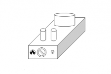
I've put everything into aluminum box. (second picture)
The problem.
Still having some buzz.
Mains toroid transformer is placed on top of the box with its base bolted underneath top surface for a cosmetic beautification. Steel cup is placed on the toroid itself. For shielding and cosmetic both.
RC filter caps are attached to the transformer base underneath.
I use simple RC filters, not regulated, PSU. B+ has four 540uF noname electrolytes and one 270uF Nichicon electrolyte cap at the end. I believe that this Nichicon is faster. I am thinking also to bypass it with ~100uF PP film motor cap.
Heater's filter has four 100,000uF electrolyte caps. It creates no ripple according to simulations. Heaters of both envelops are in serial, while inside envelopes they are paralleled. In total it it needs 12V, but actually after RC filter there is 9.8V DC, which is OK, I think.
Tubes stick out on top front in ~4 inches from mains transformer cap. Tubes are in aluminum shielding caps. (see picture)
Inside box I've separated PSU area from amp area by an aluminum compartment separator made of a beer can.
B+ wires are twisted, and heater wires are twisted too, on the way from PSU to amp.
Input female XLR is bolted to aluminum box without isolation. Pins 1,3,4 are connected together. 2" chunk of thick copper wire is soldered to XLR pin-4 and serves as circuit ground bus. Ground wires for amp cascades and PSU are soldered to this bus. Mains Earth is bolted to the case nearby power plug.
Output 1/4" unbalanced audio plug female is bolted to the case without insulation. Here I think is a problem. It should be isolated from case, should it?
Otherwise it creates loop.
Currently I am reading Grounding and Shielding Audio Devices.
Good reading, but there on fig. 4, circuit ground is connected to chassis ground nearby PSU.
So my questions are:
1 - should the input XLR pins 1,3,4 be soldered together? If not - how?
2 - should the output unbalanced 1/4" jack attached to chassis or be isolated?
3 - should the signal ground connect to chassis ground, where? directly or via some circuit? What could be that circuit?
4 - when I bring mic closer to transformer buzz increases. Is thin steel cup enough? Should I consider thicker steel?
5 - Should I consider thicker aluminum or steel for the compartment separator?
Attachments
..
So my questions are:
1 - should the input XLR pins 1,3,4 be soldered together? If not - how?
2 - should the output unbalanced 1/4" jack attached to chassis or be isolated?
3 - should the signal ground connect to chassis ground, where? directly or via some circuit? What could be that circuit?
4 - when I bring mic closer to transformer buzz increases. Is thin steel cup enough? Should I consider thicker steel?
5 - Should I consider thicker aluminum or steel for the compartment separator?
#1, On he input XLR, pin 1 is ground, conect that to the chassis as close to the input jack as you can. It is simply a sheild that does not cary any audio What is pin 4? You must mean the shell. Yes conect that to the same place as pin one.
But the SIGNAL pins 2 and 3 are NEVER grounded. NEVER ground the signal pins.
#2. Keep it isolated. Attaching it to the chassis provides two paths for the ground current. You want only one.
Trying to shield using metal chassis parts is not going to help if yo have grounded pin 2 or 3
Check this out:
http://www.ianbell.ukfsn.org/EzTubeMixer/docs/EzTubeMixer/SimpleMixer/grounding101v2.pdf
Cheers
Ian
http://www.ianbell.ukfsn.org/EzTubeMixer/docs/EzTubeMixer/SimpleMixer/grounding101v2.pdf
Cheers
Ian
- Status
- This old topic is closed. If you want to reopen this topic, contact a moderator using the "Report Post" button.
- Home
- Amplifiers
- Tubes / Valves
- Ribbon Microphone Preamp