Those thermistors belong to the protection circuit (temperature sensors). However, protection controls only the speakers' relay.
Let's check the PSU first. The original PSU assumes the driver boards are powered by the regulated supplies - points j (+57V) and i (-57V). The output boards are powered by the separate unregulated supplies - points a (+55V) and c (-55V), plus b and c for the other channel.
Is this the way the boards are actually connected now?

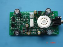
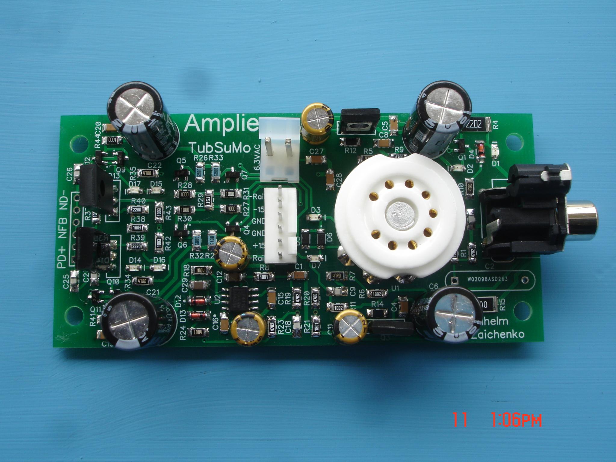
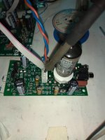
I hope SMD will be happy living near the valve thermal conditions.Nice! Tube socket on the board with lots of SMD parts looks especially cool")

Last edited:
tribute 3000
@valery
Yes that is how the driver and output boards are powered. In my haste I didn't post all the info from that thermistor connections. It looks like the e,g connections from the thermistor connect to terminal 26 (f) which connects to the meter board and is also the PSU connection for the driver boards. Terminal 26 is the connection I used for the Tribute 3000 driver boards + supply.
Terminal 26 is the same connection I used to power the driver board separately and they worked fine. When I make the connections to the OPS something is amiss.
Attachments
Last edited:
One channel close to the finish.
Excellent job Thimios. I did not find heat to be a problem, tubes run pretty cool.
Okay, I made the connections with the thermistor in the circuit as shown and got the same result. Pulsating bulb limiter.
I'll disconnect everything and test the OPS PSU under load and see if I can learn anything.
Thanks
Is there a soft-start circuit used in this amp? What you are describing sounds like a constant resetting soft-start, possibly from a dried out timing capacitor.
Yes, there is a simple analog soft-start circuit, resulting in RL02 relay shorting 2 x paralleled 8.2R resistor in a short period of time after power-on. However, if it resets, the relay would click all the time.
The other idea - maybe the bias trimmer is set to the maximum bias position (minimum R-value)? For the minimum bias, it has to be set to the maximum value position. You can also try to increase the value R26 - some 2.2K value is going to result in zero bias.
Connect the voltmeter between the emitters of Q16 and Q17 (easy to connect the clips to the emitter resistors). What does it show as you power the amp on?
The schematic parts I posted are from the Sansui BA-2000. The tribute boards are installed in that chassis using the BA-2000 supplies.
The Bias trimmers have been set in the middle.
I just powered on, no bulb limiter. Both fuses on right channel OPS supply blew.
I think I have to remove the Tribute boards and see if I can power everything up with a separate power supply. If that works I can start to look at the sansui electronics.
The Bias trimmers have been set in the middle.
I just powered on, no bulb limiter. Both fuses on right channel OPS supply blew.
I think I have to remove the Tribute boards and see if I can power everything up with a separate power supply. If that works I can start to look at the sansui electronics.
The BA-2000 chassis is a great home for this amplifier. when completed will compete with 5 - 10k equipment. It now appears as if a transistor or entire output section may be dead on the right side.
Yopu will have to test the right VAS stage as well now. The left output board can be used for that. THere may be a bad transistor causing oscillation as well.
Yopu will have to test the right VAS stage as well now. The left output board can be used for that. THere may be a bad transistor causing oscillation as well.
I had collector shorted to the heat sink. It happened before, I think because I used self threading screws. I believe when screwed in the screw forces out an aluminum sliver that penetrates the insulator. That's my theory anyway.
I still have the oscillation though. I am going back through all the wiring I did to connect the original Sansui supplies and connections to the Tribute boards.
Eventually I'll get it sorted and I agree I think it'll be a fine amp when completed.
I still have the oscillation though. I am going back through all the wiring I did to connect the original Sansui supplies and connections to the Tribute boards.
Eventually I'll get it sorted and I agree I think it'll be a fine amp when completed.
- Home
- Amplifiers
- Solid State
- Revisiting some "old" ideas from 1970's - IPS, OPS