Hey all, what did happen to the lichstark amplifier, did anyone build it?
The
Hey!
The front-end has been built and tested a few times with excellent results.
Talking about the full amp - Lichtstark-X - it has not been built as yet, as far as I know.
Cheers,
Valery
Nice boards, Blameless topology revisited
Yep - this is a very fine variation of blameless with Hawksford-cascoded VAS and low-noise LTP at the input. Easily repeatable - my prototype worked perfectly from the first power-on. Still running it in the lab from time to time.
Hey!
The front-end has been built and tested a few times with excellent results.
Talking about the full amp - Lichtstark-X - it has not been built as yet, as far as I know.
Cheers,
Valery
Huh ) I was actually wrong - Jeff has prototyped it and published his initial test results in "Sons of VHex" thread.
I'm also going to prototype and test it in the nearest future.
Huh ) I was actually wrong - Jeff has prototyped it and published his initial test results in "Sons of VHex" thread.
I'm also going to prototype and test it in the nearest future.
Thx yes I have seen it and also looking forward to see your results😊
Thx again for a great thread.
Hi All,
In case you've missed the new thread related to the speaker cables' influence on distortion level and profile:
Influence of speaker cables on harmonic distortion with different amplifiers
Cheers,
Valery
In case you've missed the new thread related to the speaker cables' influence on distortion level and profile:
Influence of speaker cables on harmonic distortion with different amplifiers
Cheers,
Valery
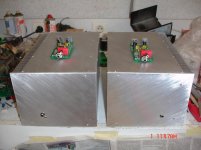
Valery,yes but now i must need some cnc work.Thimios - great job! Most of the metal work is done
Then the most difficult....what will be inside the box,what i can use for DC connectors, e.t.c e.t.c
Last edited:
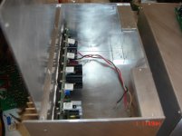
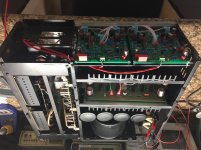
Now you're into the fun part!If your transformer will fit the amp would work out nicely with the transformer attached to the power connector end of the chassis with the supplies stacked back to back next to it. That would keep all the noisy parts away from the input end and everything in one box. Cooling would be improved if you flipped the whole thing upside down putting the output devices below the center of the heat sink.
Attachments
Aha i see Jeff, you prefer that solution....all in one box.Now you're into the fun part!If your transformer will fit the amp would work out nicely with the transformer attached to the power connector end of the chassis with the supplies stacked back to back next to it. That would keep all the noisy parts away from the input end and everything in one box. Cooling would be improved if you flipped the whole thing upside down putting the output devices below the center of the heat sink.
1)I dont think that transformer will fit.
2)I want to use the power supply as passepartout!
As for the cooling...my plan is to drill the bottom place.The upper will be logo, cnc machined ,cooling helper logo.
Any disadvantage putting the transformer,rectifier out of the box?
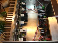
It sounds like a great looking chassis is in the works! Having the power supply in a separate box works but you need to increase the conductor size due to the extra length and you'll have a lot more area producing noise so you would need to be careful with interconnect wiring.
The optimal location for placing the output devices is slightly below center of the heat sink. Wakefield recommends 40% up from the bottom spread out the entire length of the heat sink. This will only become an issue if you are running above 60V rails though.
The optimal location for placing the output devices is slightly below center of the heat sink. Wakefield recommends 40% up from the bottom spread out the entire length of the heat sink. This will only become an issue if you are running above 60V rails though.
Does it mean that would more efficient turning this upside down??It sounds like a great looking chassis is in the works! Having the power supply in a separate box works but you need to increase the conductor size due to the extra length and you'll have a lot more area producing noise so you would need to be careful with interconnect wiring.
The optimal location for placing the output devices is slightly below center of the heat sink. Wakefield recommends 40% up from the bottom spread out the entire length of the heat sink. This will only become an issue if you are running above 60V rails though.
Does it mean that would more efficient turning this upside down??
If you flip your heat sink upside down it will put the row of output transistors right in the optimum location for cooling. When I did the layout I chose the position of the output transistors to position them correctly on a 6" tall heat sink with the transistors mounted below the board. With the heatsink mounted as you have it they are about 1.5" above the optimum position so the heat won't transfer to the bottom of the heat sink, reducing cooling efficiency.
No isn't but now rework was done.if your heatsink is symmetrical, just flip heatsink and board 180 degrees
Tribute 3000
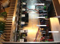
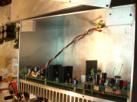
I’m back at the Tribute 3000 and am having a problem. I have the driver boards up and running but I have an issue when I wire it all into the chassis. With a bulb in series with the mains the bulb goes bright then dims then pulsates bright, dim about once a second. I haven’t left it powered on more than a few seconds but even without the bulb in series I can see my bench lights pulsate a little. Looking at the schematic I remembered I don’t have the thermistor from the original output transistors connected. Could this be the problem? Without that, part of the protection circuit is incomplete.
Thank you for any ideas
Attachments
Last edited:
- Home
- Amplifiers
- Solid State
- Revisiting some "old" ideas from 1970's - IPS, OPS