ok, so even good distributors like element14 make mistakes, probaby a human error while packaging small qty. I always get confused with onsemi part nos, be it to-220's or bigger power devices, and I have to refer to datasheet.
I bought some components from element14.
I built up 4 amps and none worked.
So had to go through whole amp checking each component with a meter.
One of the resistors was wrong value despite package having the value it should have been.
So had 4 amps to pull out the offending resistors.
Sadly there is no comeback as we accept their terms and conditions.
I rang them up to tell them their parts bin was wrong but all they would do was apologise.
A yet haven't had a wrong component from RS but occasionally there is something missing from the order despite being on list.
I would rather a component was missing to being wrong part.
Hi gang, made a few adjustments.
I’ve adjusted the PSU, am now using the on board rectifier, measuring 55 VDC Rail. Any suggestions how to drop 5V?
Swapped R5 12K to 15K.
Added extra 33R to R8, with the recommended 50R on the schematic.
So..
I can’t seam to adjust the bias. I get just under 1 mV DC @ R-8 & R19
Still getting cross over distortion, maybe a little worse.
All suggestions welcome, thanks everybody.
Attachments
Do not use a trimmer and a fixed resistor(R8)in the same time.Hi gang, made a few adjustments.
I’ve adjusted the PSU, am now using the on board rectifier, measuring 55 VDC Rail. Any suggestions how to drop 5V?
Swapped R5 12K to 15K.
Added extra 33R to R8, with the recommended 50R on the schematic.
So..
I can’t seam to adjust the bias. I get just under 1 mV DC @ R-8 & R19
Still getting cross over distortion, maybe a little worse.
All suggestions welcome, thanks everybody.
Use the trimmer only!
Hi gang, made a few adjustments.
I’ve adjusted the PSU, am now using the on board rectifier, measuring 55 VDC Rail. Any suggestions how to drop 5V?
Swapped R5 12K to 15K.
You don't need to drop 5V. With 55V you will only have a little more power, which is beneficial. All you have to do is to see that at the output of amp taken at the positive side of output cap (output side of R18), there is approximately 27,5V. You should install 50k trimmer (connected as rheostat) in place of R5 and adjust it to have app. 27,5V. That's it.
Used the good trannies from board 2 and fired up board 1.
Set bias at about 20mA, nice and stable.
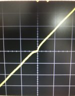
Got a badly clipped output at 0.3v in so dropped it to about 0.1v which got me a sine wave. (I'll check out the voltages later).
Started to get oscillations.. shut it off quick.
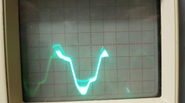
Ran the board again without any input and got the output in attached photo.
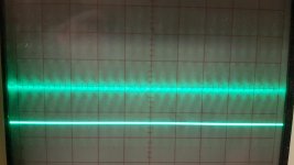
The SMPS I am using appears to be noisy. Second picture is the scope on the SMPS output.
I think I might order up a transformer and the diodes to run on-board rectification and try again then. Waiting for an enclosure to arrive anyway.
*But I did get a sine wave*
*And only had to change out the incorrect driver*
")
Set bias at about 20mA, nice and stable.
Got a badly clipped output at 0.3v in so dropped it to about 0.1v which got me a sine wave. (I'll check out the voltages later).
Started to get oscillations.. shut it off quick.
Ran the board again without any input and got the output in attached photo.
The SMPS I am using appears to be noisy. Second picture is the scope on the SMPS output.
I think I might order up a transformer and the diodes to run on-board rectification and try again then. Waiting for an enclosure to arrive anyway.
*But I did get a sine wave*
*And only had to change out the incorrect driver*
Attachments
All you have to do is to see that at the output of amp taken at the positive side of output cap (output side of R18), there is approximately 27,5V. You should install 50k trimmer (connected as rheostat) in place of R5 and adjust it to have app. 27,5V. That's it.
Good idea to install a trimmer for setting the voltage center.
For 55v, the sim puts R5 at around 14k.
Good idea to install a trimmer for setting the voltage center.
For 55v, the sim puts R5 at around 14k.
Use a 50K multiturn ,connect as reostat(cender pin together with one of the other pins).
Adjust for half d.c voltage in the primary side of the output capacitor.
Desolder the trimmer,measure the resistans.Use a fixed resistor with the closest value.
it is convenient to have a resistor packages such as this one 3120pcs 156Values Electric Unit 1/4W Power Metal Film Resistor Kit 1R 10M 1% Tolerance Assortment Set 1ohm 10Mohm samples pack-in Resistors from Electronic Components & Supplies on Aliexpress.com | Alibaba Group
especially when one quickly needs to change values and see.
especially when one quickly needs to change values and see.
it is convenient to have a resistor packages such as this one 3120pcs 156Values Electric Unit 1/4W Power Metal Film Resistor Kit 1R 10M 1% Tolerance Assortment Set 1ohm 10Mohm samples pack-in Resistors from Electronic Components & Supplies on Aliexpress.com | Alibaba Group
especially when one quickly needs to change values and see.
Order placed!
Thank you all for your comments, I’m learning and am very grateful . So I’ve removed the extra bias resistor that I mistakenly installed next to the 50R trimmer. Need to order a few more parts, 50K trimme, a few different value resistors and the components to populate second channel. They should be here by the end of week. While I’m at it I think order one of those resistor assortment packs that was suggested, it will be handy down the road.
Looking forward to seeing Prasi and avtech get there’s running. Happy soldering guys.
. So I’ve removed the extra bias resistor that I mistakenly installed next to the 50R trimmer. Need to order a few more parts, 50K trimme, a few different value resistors and the components to populate second channel. They should be here by the end of week. While I’m at it I think order one of those resistor assortment packs that was suggested, it will be handy down the road. Looking forward to seeing Prasi and avtech get there’s running. Happy soldering guys.
Hi Ivan, your boards look different to mine, different component values, and jumped resistors. Have you built quasi designs before? I looked up “base stoppers” to better understand there function, I’m still learning. How did you know it would work without them? Thanks for all your advice
Base stoppers are there to provide stability with fast output transistors like those marked on APEX schematic. Since I decided to use slow output devices there is no need to use them. Most old current feedback circuits don't have them because in those days there was no fast output transistors. Most components on my board are as per schematic. Quasi outputs are here for "authenticity". In fact I would prefer Darlington output stage for this amp because I buy output transisitors in complementary pairs so now I have PNP transisitors that will hardly be used in another amp, just a waste of resources, now I have surplus PNP outputs.
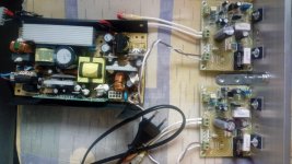
Test setup with SMPS.
Hi ivanlukic, never i have used a smps to power an amplifier.(except a salvaged car amplifier).
Is it noisy? I see a general use smps not for audio, can you tell if you prefer this against linear power supply?
No, it's not noisy. I don't hear anything in loudspeakers. To me audio amplifiers sound always better with SMPS, especially if it is good dedicated SMPS for audio. The only problem is susceptibility of other appliances to ultrasonic noise radiated from SMPS. I am not the only one who noticed that they sound better with audio amplifiers than linear supply! The only problem is that linear supply can be built by almost any diy-er and design and assembly of SMPS for audio is only for very few specialists. SMPS has enormous reserves of current and they can deliver it instantly to amp. The amp has more authority with SMPS. Equivalent linear PSu should be gigantic to compete with SMPS.
A French builder of QUAD 405 clone noticed improvement in sound quality when he used SMPS to power it.
A French builder of QUAD 405 clone noticed improvement in sound quality when he used SMPS to power it.
Last edited:
- Home
- Amplifiers
- Solid State
- Retro Amp 50W Single Supply