Oliver's latest Red Baron board has two jumpers. One of those jumpers (I believe) changes the pin voltage to accept the signals from Ian's PCM board. Maybe that's the problem?...
OTOH...I'd HIGHLY recommend the latest Red Baron board Oliver has come out with. The u.fl connection from Ian's board to The Red Baron raises the game to another level....
OTOH...I'd HIGHLY recommend the latest Red Baron board Oliver has come out with. The u.fl connection from Ian's board to The Red Baron raises the game to another level....
Hi dtses,
While I haven't got my dac operational just yet, I'm looking at your photo and noticed a couple things. The strings of diodes that replaced the 1K resistors look to be in parallel and the 3 in a string should be in series.
cheers ZUM911,
thanks for help and sorry for bad pic, these are in series, of course.
The dac works perfectly with Amanero USB board (tried without Ian's board).
Oliver's latest Red Baron board has two jumpers. One of those jumpers (I believe) changes the pin voltage to accept the signals from Ian's PCM board. Maybe that's the problem?...
not sure, maybe Oliver could comment please?
Received PCM board
Hi,
I have received the PCM board but I haven't installed it yet as my setup is working properly with the TPAs SRC4192 board. I am working in some other projects and hadn't had enough time for this. In my opinion is a problem of compatibility between TPA and Oliver DAC. I tried all configs possible in the WM8804 board without success. Trying I installed the SRC4192 and all fixed... But as I have said in other posts, I have no idea why....
Regards,
Jorge
thanks for your help triode_al!
1. it's v4.0 with separate i2s grounding.
2. how to do that?
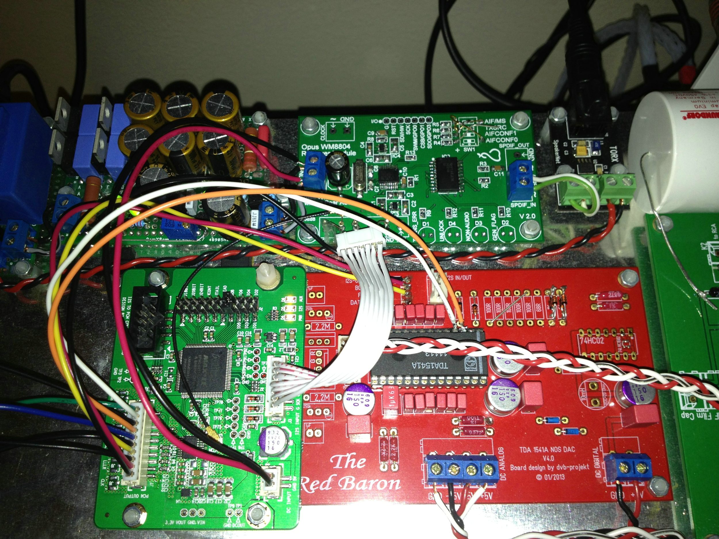
here is how the TPA and PCM boards are connected:
BCK -> SCK
SCK -> MLCK
LRCK -> WS
DOUT -> SD
GND -> GND (tried to disconnect, doesn't influence on anything)
pcm board and TDA are connected as in the Ian's manual here. DL and DR are soldered directly to TDA chip.
Tried to set the board at half speed, no difference in hissing and all three leds are on (at least that should be good).
Frankly speaking I'm not sure it's something related to Ian's board or connection, it looks more like another issue with TPAs spdif pcb.
I have found a similar issue in Subbu DAC thread where one member experienced similar noise. Turned out to be a dead 12mhz crystal. Does it worth replacing mine perhaps?
jcastellano,
have you already received the PCM board? I guess you are my last hope, if it won't work properly for you as well, then the only workaround would be to replace TPAs board I suppose.
Hi,
I have received the PCM board but I haven't installed it yet as my setup is working properly with the TPAs SRC4192 board. I am working in some other projects and hadn't had enough time for this. In my opinion is a problem of compatibility between TPA and Oliver DAC. I tried all configs possible in the WM8804 board without success. Trying I installed the SRC4192 and all fixed... But as I have said in other posts, I have no idea why....
Regards,
Jorge
PCM Input with Red Baron DAC Module
Oliver's latest Red Baron board has two jumpers. One of those jumpers (I believe) changes the pin voltage to accept the signals from Ian's PCM board. Maybe that's the problem?...
OTOH...I'd HIGHLY recommend the latest Red Baron board Oliver has come out with. The u.fl connection from Ian's board to The Red Baron raises the game to another level....
@ All
If you want to use Ian´s I2S to PCM module to raise the SQ to the maximum, you need the Red Baron V5.0.
Only this version has the possibility to use the simultaneous mode (two jumpers),
a separate input for DATA/R and the highly recommended u.fl connectors!
Cheers,
Oliver

If you want to use Ian´s I2S to PCM module to raise the SQ to the maximum, you need the Red Baron V5.0.
Only this version has the possibility to use the simultaneous mode (two jumpers),
a separate input for DATA/R and the highly recommended u.fl connectors!
Cheers,
Oliver
Last edited:
@ All
If you want to use Ian´s I2S to PCM module to raise the SQ to the maximum, you need the Red Baron V5.0.
Only this version has the possibility to use the simultaneous mode (two jumpers),
a separate input for DATA/R and the highly recommended u.fl connectors!
Cheers,
Oliver
What about isolation?
@ All
If you want to use Ian´s I2S to PCM module to raise the SQ to the maximum, you need the Red Baron V5.0.
which mod do I need to add for version 4 to become friends with PCM module?
I've removed the connection between legs 27 & 28 on pcb and added -5v to pin 27, but still got same distortions as I reported here.
What about isolation?
Witch isolation did you mean?
which mod do I need to add for version 4 to become friends with PCM module?
I've removed the connection between legs 27 & 28 on pcb and added -5v to pin 27, but still got same distortions as I reported here.
If you click on the V5.0 schematics on the bottom of my blog side, you could see thee needed connections
")
Witch isolation did you mean?
If you click on the V5.0 schematics on the bottom of my blog side, you could see thee needed connections
thanks!
Could it be that the problem of distortions lays in missing DEM oscillator modification?
Pin 27 is attached to negative rail, DL & DR are connected directly to TDAs pins as Ian advised, but I get same distortions and similar hissing I had with TPAs module.
I would very appreciate any help as I've already run out of patience and ideas why the damn TDA works fine with Amanero, but fails with new PCM module...
Last edited:
thanks!
Could it be that the problem of distortions lays in missing DEM oscillator modification?
Pin 27 is attached to negative rail, DL & DR are connected directly to TDAs pins as Ian advised, but I get same distortions and similar hissing I had with TPAs module.
I would very appreciate any help as I've already run out of patience and ideas why the damn TDA works fine with Amanero, but fails with new PCM module...
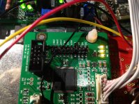
It is hard to see on your photo, if the switch setting is correct.
Look to the photo of my TPA i had before:
An externally hosted image should be here but it was not working when we last tested it.
Only the upper switch must be set to the left position. All others must be set to the right position.
If your setting is ok, i run out of ideas whats up with the TPA...
Hi Oliver!
I've already ordered another board for spdif input, so TPA will be left for another project. Funny thing is that I've tried to set the switch as on your pic, but was still unlucky.
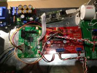
Now I've been trying to connect PCM module with Amanero, which works fine with TDA alone. Everything is connected as I've mentioned in PCM thread here and here:
Pretty similar situation as with TPA module and I would even begin thinking that there is something with my TDA pcb, however how does the Amanero board work fine then?!
I've already ordered another board for spdif input, so TPA will be left for another project. Funny thing is that I've tried to set the switch as on your pic, but was still unlucky.
Now I've been trying to connect PCM module with Amanero, which works fine with TDA alone. Everything is connected as I've mentioned in PCM thread here and here:
Pin 27 is attached to negative rail, DL & DR are connected directly to TDAs pins as Ian advised, but I get same distortions and similar hissing I had with TPAs module.
Pretty similar situation as with TPA module and I would even begin thinking that there is something with my TDA pcb, however how does the Amanero board work fine then?!
Twisted Pear Audio S/PDIF Tranceiver Module DIP settings
The correct settig without the DIP switch is:
- SW1 Upper connector left (R5) to lower connector right (+)
- all other SW1 connectors left (R6, R7, R8) to upper connector right (GND)
With this setting you´ll get 16bit I2S output (BCK, LRCK, DOUT, GND).
It is hard to see, if the wire is soldered correct...
Funny thing is that I've tried to set the switch as on your pic, but was still unlucky.
The correct settig without the DIP switch is:
- SW1 Upper connector left (R5) to lower connector right (+)
- all other SW1 connectors left (R6, R7, R8) to upper connector right (GND)
With this setting you´ll get 16bit I2S output (BCK, LRCK, DOUT, GND).
It is hard to see, if the wire is soldered correct...
many thanks, Oliver!
I'll install DEM mod and report in a few days if it helps.
these are the exact settings I've tried with!
I'll install DEM mod and report in a few days if it helps.
The correct settig without the DIP switch is:
- SW1 Upper connector left (R5) to lower connector right (+)
- all other SW1 connectors left (R6, R7, R8) to upper connector right (GND)
these are the exact settings I've tried with!
As I'm planning to build Red Baron TDA1541A DAC with all Salas shunt regulators and WaveIO USB to I2S, I was wondering how does Tube-i-zator output stage sound?
Did anyone tryed different tube output stage? Maybe with 6N1P-EV, E88CC? And how do they compare to Tube-i-zator?
Thanks in advance
Did anyone tryed different tube output stage? Maybe with 6N1P-EV, E88CC? And how do they compare to Tube-i-zator?
Thanks in advance
cheers,
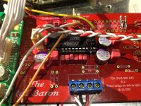
it's getting hotter and more tricky!
DEM mode has been implemented (6k8 resistors and 2.2nf cap are below the board), same distortions to follow
Double check Red Baron board, all seem to be fine. Double checked connection, again everything looks to be fine.
Triple checked power supplies and voltages on TDA chip, looks fine.
I wonder if it's possible to connect PCM board at all
Attachments
Hello to everyone!
It seems to be my first post in here. I'm starting to build my first RedBaron and will have few questions.
The first one is if anyone tried to use Nichicon Polymer Capacitors in place od Elna Silmic's in shunt regs? There are 25V rated caps up to 330uF and 35V rated caps up to 150uF available at Mouser. The 35V could be used in parallel to get 220uf or even more. Any idea if they could improve the sound?
Best regards,
Maciek
Hello to everyone!
It seems to be my first post in here. I'm starting to build my first RedBaron and will have few questions.
The first one is if anyone tried to use Nichicon Polymer Capacitors in place od Elna Silmic's in shunt regs? There are 25V rated caps up to 330uF and 35V rated caps up to 150uF available at Mouser. The 35V could be used in parallel to get 220uf or even more. Any idea if they could improve the sound?
Best regards,
Maciek
Hi Maciek,
yes, you can use two 150uF in parallel to increase capacitance.
But I really doubt you will have any improvement in sound, because Salas shunt regulator has as twice as lower output impedance than any electrolytic 220uF - 330uF capacitor.
I guess, increase of capacitance on output simply will be "over engineering" here.
I would better keep Nichicon solid polymer capacitors for Red Baron.
And for shunt regulator I would use Panasonic FM 220uF/35V (EEU-FM1V221L in same Mouser). Ones have quite low impedance and long life duration - 3000h/105C.
Best wishes
Saulius
Hi Saulius,
Thanks a lot for your answer. I'll buy Nichicon polymer capacitors for RedBaron anyway. I asked because I have a few Silmic's laying around and was considering if to use them or to buy something different.
Regards,
Maciek
- Status
- This old topic is closed. If you want to reopen this topic, contact a moderator using the "Report Post" button.
- Home
- Group Buys
- "Reference" TDA1541A DAC with I2S-BUS architecture