TDA1541
Yes, it is a quote") .
.
But look deeper, to characteristics on datasheet, part "Inputs":
fWS word select input pin 2 - MAX 200 kHz
fLE latch enable input 1 - MAX 200 kHz
I have ever seen only one implementation of "8x oversampling" - in Sony CDP-337ESD: two TDA1541A with paralleled outputs and different I2S streams from digital filter chip, both TDA1541 are 4x oversampling but second chip receives inverted WS clock (so DA sampling time in second chip is shifted by WS/2).
Here it is described in post#1 of DIYAUDIO thread : http://www.diyaudio.com/forums/digital-source/226480-sony-staggered-twin-tda1541.html.
One of mine CD players is same CDP-337ESD , but I have converted it to non oversampling by extra circuitry, just to avoid this "staggering" and digital filtering.
Difference between original "8X oversamping" and NOS version is quite sensible - at first I made both modes selectable by switch just to make A-B comparison, but later fixed NOS solution.
Concerning Ian's I2S-PCM board - it worked with TDA1541 in half speed mode, but fLE was 352.8kHz.
Half speed (by diagrams in user manual of I2S-PCM board) means twice slower data loading to TDA1541, but fLE is still higher than 200kHz...
Maybe this is related to 3.3V LVTTL signal (in case of Olivers set - even 3.3V attenuator), but anyway it is serious overclocking...
TDA1541A sheet:
Quote:
The high maximum input bit-rate and fast setting facilitates application in 8 x oversampling systems (44.1 kHz to 352.8 kHz or 48 kHz to 384 kHz) with the associated simple analog filtering function (low order, linear phase
filter).
Yes, it is a quote
. But look deeper, to characteristics on datasheet, part "Inputs":
fWS word select input pin 2 - MAX 200 kHz
fLE latch enable input 1 - MAX 200 kHz
I have ever seen only one implementation of "8x oversampling" - in Sony CDP-337ESD: two TDA1541A with paralleled outputs and different I2S streams from digital filter chip, both TDA1541 are 4x oversampling but second chip receives inverted WS clock (so DA sampling time in second chip is shifted by WS/2).
Here it is described in post#1 of DIYAUDIO thread : http://www.diyaudio.com/forums/digital-source/226480-sony-staggered-twin-tda1541.html.
One of mine CD players is same CDP-337ESD , but I have converted it to non oversampling by extra circuitry, just to avoid this "staggering" and digital filtering.
Difference between original "8X oversamping" and NOS version is quite sensible - at first I made both modes selectable by switch just to make A-B comparison, but later fixed NOS solution.
Concerning Ian's I2S-PCM board - it worked with TDA1541 in half speed mode, but fLE was 352.8kHz.
Half speed (by diagrams in user manual of I2S-PCM board) means twice slower data loading to TDA1541, but fLE is still higher than 200kHz...
Maybe this is related to 3.3V LVTTL signal (in case of Olivers set - even 3.3V attenuator), but anyway it is serious overclocking...
I have ever seen only one implementation of "8x oversampling" - in Sony CDP-337ESD:
That is indeed a surprise, but the link says
so that is simultaneous modeThe mode which works faster has separate L and R data inputs.
Last edited:
TDA1541
About what link you are talking?
It is obvious that in simultaneous mode data input rate can be higher than in time multiplexed mode because of usage of both DATA L and DATA R instead of multiplexed DATA only (twice less bottleneck).
Each input on pins 3 and 4 can operate up to 6.4 Mbit/sec (TDA1541A). So calculated "official" limit of sampling rate here is 400 kHz (without 200kHz limitation of fLE in datasheet), while multiplexed mode limitation is 200kHz only.
Possibly here was an error in Philips datasheet.
That is indeed a surprise, but the link says
Quote:
"The mode which works faster has separate L and R data inputs.
so that is simultaneous mode
About what link you are talking?
It is obvious that in simultaneous mode data input rate can be higher than in time multiplexed mode because of usage of both DATA L and DATA R instead of multiplexed DATA only (twice less bottleneck).
Each input on pins 3 and 4 can operate up to 6.4 Mbit/sec (TDA1541A). So calculated "official" limit of sampling rate here is 400 kHz (without 200kHz limitation of fLE in datasheet
), while multiplexed mode limitation is 200kHz only. Possibly here was an error in Philips datasheet.
About what link you are talking?
the staggered link!
hello jcastellano,
any news with a buffer from Oliver? Did you manage to work it properly without SRC4192?
I'm asking as in the same situation and don't know what to do. Already checked TPA transceiver for dozen of times and seems it's ok. The DAC works fine with Amanero, but with TPA's board I get similar hiss as you did.
No way without SRC4192
Hi friends,
Sorry for no updating...
It has been impossible to make it work. Neither the buffer or the 3.3v mod worked. And I do not know how Oliver did it to make it work.
This is DIY so not all configurations are equal and every diyer make same things so no complaint by this side.
I think that the issue rely on the 24 bits output from the WM8804 TPA board. It is not a issue of frequency AFAIK. With the SRC4192 you can configure to 16bit I2S output beacuse you have more switches to play with ( although you have to read carefully the chip datasheet to make the idea of how to make it work). I bought one spdif to I2S board from ebay that can be configured to 16bit I2S and worked fine but I had to left the TPA boards due to space left for the receiver. Maybe there is a config for the TPAWM8804 to output 16 bit I2S and the SRC4192 is not necesary but I do not know how to do it after several tryouts and studiing carefully the datasheet and the "spartan" manual of the TPA boards.Also no complaint by this side about TPA due to they state clearly that this is DIY and their boards are tailored mainly for them so, use out of the TPA cloud is "alone in the dark".
Now it is working fineand I am very happy with it  .
.
It is a little overkill all those Salas shunts in my opinion. Those boards made me mad about space and I had to make a two box solution with a diy cable with two military spec 12 pins connectors for all the secondaries needed. A BIG NIGHTMARE....!!!
Sorry for the brick and sorry for my English....
hello jcastellano,
any news with a buffer from Oliver? Did you manage to work it properly without SRC4192?
I'm asking as in the same situation and don't know what to do. Already checked TPA transceiver for dozen of times and seems it's ok. The DAC works fine with Amanero, but with TPA's board I get similar hiss as you did.
Hi friends,
Sorry for no updating...
It has been impossible to make it work. Neither the buffer or the 3.3v mod worked. And I do not know how Oliver did it to make it work
.This is DIY so not all configurations are equal and every diyer make same things so no complaint by this side.
I think that the issue rely on the 24 bits output from the WM8804 TPA board. It is not a issue of frequency AFAIK. With the SRC4192 you can configure to 16bit I2S output beacuse you have more switches to play with ( although you have to read carefully the chip datasheet to make the idea of how to make it work). I bought one spdif to I2S board from ebay that can be configured to 16bit I2S and worked fine but I had to left the TPA boards due to space left for the receiver. Maybe there is a config for the TPAWM8804 to output 16 bit I2S and the SRC4192 is not necesary but I do not know how to do it after several tryouts and studiing carefully the datasheet and the "spartan" manual of the TPA boards.Also no complaint by this side about TPA due to they state clearly that this is DIY and their boards are tailored mainly for them so, use out of the TPA cloud is "alone in the dark".
Now it is working fine
and I am very happy with it .It is a little overkill all those Salas shunts in my opinion. Those boards made me mad about space
and I had to make a two box solution with a diy cable with two military spec 12 pins connectors for all the secondaries needed. A BIG NIGHTMARE....!!!Sorry for the brick and sorry for my English....
I have a problem in getting the high speed buffer up and running.
I have connected the buffer to +5V and have the inputs and outputs via CAT6 cable [and Ethernet plugs so I can easily dis/connect things ..].
I used the connections 1,2,3 at random order on the board (in fact 1,2,3 = BCK, WS, DTA). My source is an XMOS card - not a pear as in the Bernard's picture (if I am correct it outputs 3,3V max I2S).
what can be wrong?
An externally hosted image should be here but it was not working when we last tested it.
I have connected the buffer to +5V and have the inputs and outputs via CAT6 cable [and Ethernet plugs so I can easily dis/connect things ..].
- The output is digital garbage, the DAC board does not lock.
- The board works without the buffer in between but not to high speeds
I used the connections 1,2,3 at random order on the board (in fact 1,2,3 = BCK, WS, DTA). My source is an XMOS card - not a pear as in the Bernard's picture (if I am correct it outputs 3,3V max I2S).
what can be wrong?
Last edited:
I have a problem in getting the high speed buffer up and running.
An externally hosted image should be here but it was not working when we last tested it.
I have connected the buffer to +5V and have the inputs and outputs via CAT6 cable [and Ethernet plugs so I can easily dis/connect things ..].
I tried a separate 7805 on the board with 100 uF and 2n2 ECHU SMD-decoupling, also no improvement (worse in fact).
- The output is digital garbage, the DAC board does not lock.
- The board works without the buffer in between but not to high speeds
I used the connections 1,2,3 at random order on the board (in fact 1,2,3 = BCK, WS, DTA). My source is an XMOS card - not a pear as in the Bernard's picture (if I am correct it outputs 3,3V max I2S).
what can be wrong?
Hi,
When I tried the UHS buffer this was my connections:
I2S Converter --> Buffer --> DAC Module
Data --> Buffer input - Buffer output --> Data DAC module PIN 2
LRCLK --> Buffer input - Buffer output --> FS DAC module PIN 3
BCK --> Buffer input - Buffer output --> BCK DAC module PIN 1
I copied from the forum but I do not remember the thread number. It was a comment from Oliver so...
Does your XMOS card outputs 24 bits? Can you change it to 16 bits? Maybe your problem is the same as mine...
Regards...
Jorge
Last edited:
Hi,
When I tried the UHS buffer this was my connections:
I2S Converter --> Buffer --> DAC Module
Data --> Buffer input - Buffer output --> Data DAC module PIN 2
LRCLK --> Buffer input - Buffer output --> FS DAC module PIN 3
BCK --> Buffer input - Buffer output --> BCK DAC module PIN 1
I copied from the forum but I do not remember the thread number. It was a comment from Oliver so...
Does your XMOS card outputs 24 bits? Can you change it to 16 bits? Maybe your problem is the same as mine...
Regards...
Jorge
Yes my XMOS can only do 24 bits. The DAC chip discards anything beyond the 16th bit. It works good (and nice sounding) up to 96KHz, but not above that.
I have added a local ground AND on the UHS board,
+ I had a bad solder joint
on DTA but now it works - but no improvement in speed over the bare XMOS unit.
My hypothesis was: that the DAC needs a higher signal swing at higher freq's.
Maybe an XMOS (lorries) will be better because it is really adaptive in 24 or 16 bits.
Hi friends,
Sorry for no updating...
It has been impossible to make it work. Neither the buffer or the 3.3v mod worked. And I do not know how Oliver did it to make it work
sounds like you found the main problem... Bad thing is that TPA's board should be swapped with something else now. I wonder if Ian's spdif interface board will be good here
Another alternative is to buy cheap assembled board like that. Btw, could the problem with 24bits to be solved via Ian'sI2S to PCM converter board. At least from description it clearly stated:
1. Support 16,18,20,24 bit PCM format output
2. Accept 16 to 32bit I2S input signals with SCK from 32*Fs to 64*Fs
So perhaps it worths trying at least and hoping for a miracle
A question to Oliver most likely, according to 9th page of manual here, the PCM daughter board should be able to install without a FIFO kit, have you tried so? or I misunderstood something?
This SPDIF to I2S works...
Hi Friends,
This board worked like a champion...
Search ebay for these exact words "WM884 S/PDIF TOSLINK to IIS Converter I2S Coded Project integration DIY"
But I had no way to fit it in the space left for the receiver because I always thought to use the TPA's board. I think that Ian's I2S to PCM will be the best option using the TPA's WM8804 board and no need to resample with the SRC4192 one. Ian's board can be used by itself and I am waiting for it to arrive and check if his board works and if it better soundwise than the SRC4192 already fitted.
I am still wondering how Oliver managed to make it work...
Regards,
Jorge
sounds like you found the main problem... Bad thing is that TPA's board should be swapped with something else now. I wonder if Ian's spdif interface board will be good here
Btw, could the problem with 24bits to be solved via Ian'sI2S to PCM converter board. At least from description it clearly stated:
1. Support 16,18,20,24 bit PCM format output
2. Accept 16 to 32bit I2S input signals with SCK from 32*Fs to 64*Fs
So perhaps it worths trying at least and hoping for a miracle
A question to Oliver most likely, according to 9th page of manual here, the PCM daughter board should be able to install without a FIFO kit, have you tried so? or I misunderstood something?
Hi Friends,
This board worked like a champion...
Search ebay for these exact words "WM884 S/PDIF TOSLINK to IIS Converter I2S Coded Project integration DIY"
But I had no way to fit it in the space left for the receiver because I always thought to use the TPA's board. I think that Ian's I2S to PCM will be the best option using the TPA's WM8804 board and no need to resample with the SRC4192 one. Ian's board can be used by itself and I am waiting for it to arrive and check if his board works and if it better soundwise than the SRC4192 already fitted.
I am still wondering how Oliver managed to make it work...
Regards,
Jorge
Last edited:
hi Jorge,
I'm in GB too. Payment has been made so I hope to receive it soon.
Don't have any free place as well, however the one you've mentioned looks not that big, though I didn't find any dimensions in the listing. I wonder if there would be a noticeable difference with Ian's or TPA boards?!
I'm in GB too. Payment has been made so I hope to receive it soon.
Don't have any free place as well, however the one you've mentioned looks not that big, though I didn't find any dimensions in the listing. I wonder if there would be a noticeable difference with Ian's or TPA boards?!
Not too much, but still...
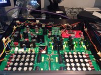
Hi Dtses,
Is a little bigger in all dimensions, about 1cm more (near half an inch) and my real state in the really big Hifi2000 case was very short. So...I am going to try to stay with the WM8804 TPA's board and Ian's I2S to PCM above the former with standoffs.
Some pics....
Regards,
Jorge
hi Jorge,
I'm in GB too. Payment has been made so I hope to receive it soon.
Don't have any free place as well, however the one you've mentioned looks not that big, though I didn't find any dimensions in the listing. I wonder if there would be a noticeable difference with Ian's or TPA boards?!
Hi Dtses,
Is a little bigger in all dimensions, about 1cm more (near half an inch) and my real state in the really big Hifi2000 case was very short. So...I am going to try to stay with the WM8804 TPA's board and Ian's I2S to PCM above the former with standoffs.
Some pics....
Regards,
Jorge
Attachments
Hi,
Can someone please help with some advice on this R-Core transformer to use with the red baron v5,?
What is needed:
12v 1a x 3
20v 1a x 1
50W R-Core Transformer
Input Voltage AC 0~115v~230V, SCN (4 wires)
Output 1: AC 0~20V 0.6A, 0~20V 0.6A (4 wires)
Output 2: AC 0~15V 0.6A, 0~15V 0.6A (4 wires)
Output 3: AC 0~12V 0.6A (2 wires)
would it be any good to power this Dac?
Thanks
cheers,
good news, I've got Ian's i2s to pcm board. Bad news, I still got the same hissing after connecting everything according to the manual. The jumper is set to "JOB". Any ideas except putting TPA's i2s converter board to the rubbish bin?!
- You might have a large earth loop: the TDA1541 board (older version I have) does not have a earth pad for the I2S, so the 'signal' is sort of is floating; the return must go via somewhere else (the generic earth). The result is unpredictable behavior of the rising edges (and maybe even resonances); this imho can theoretically be worse than jitter. If this is the case in your build, then this can lead to loss of detection. So 'scratch an earth pad' directly next to the connector as I did and connect the 'G' there.
- Also you might reduce the 'speed' to 88 kHz - in my current XMOS implementation I get only hiss or one channel only above 96 kHz ;
- in the channel that works the MSB seems to lack then too sometimes; it is not stable
So I2S is not as simple as I hoped.
Bernard himself has a very small and tight constellation looking at his pictures (stacking) while I - like most people - have it laid out on the bottom of a box.
Bernard, I hope I am not offending you
thanks for your help triode_al!
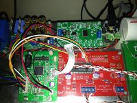
1. it's v4.0 with separate i2s grounding.
2. how to do that?
here is how the TPA and PCM boards are connected:
BCK -> SCK
SCK -> MLCK
LRCK -> WS
DOUT -> SD
GND -> GND (tried to disconnect, doesn't influence on anything)
pcm board and TDA are connected as in the Ian's manual here. DL and DR are soldered directly to TDA chip.
Tried to set the board at half speed, no difference in hissing and all three leds are on (at least that should be good).
Frankly speaking I'm not sure it's something related to Ian's board or connection, it looks more like another issue with TPAs spdif pcb.
I have found a similar issue in Subbu DAC thread where one member experienced similar noise. Turned out to be a dead 12mhz crystal. Does it worth replacing mine perhaps?
jcastellano,
have you already received the PCM board? I guess you are my last hope, if it won't work properly for you as well, then the only workaround would be to replace TPAs board I suppose.
Attachments
Last edited:
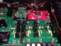
Hi dtses,
While I haven't got my dac operational just yet, I'm looking at your photo and noticed a couple things. The strings of diodes that replaced the 1K resistors look to be in parallel and the 3 in a string should be in series. You have the BAT43 parts in as well as the 12K resistors, both were recommended to be removed. Not sure about the last 2 being a problem but I would try fixing the diode strings.
While I haven't got my dac operational just yet, I'm looking at your photo and noticed a couple things. The strings of diodes that replaced the 1K resistors look to be in parallel and the 3 in a string should be in series. You have the BAT43 parts in as well as the 12K resistors, both were recommended to be removed. Not sure about the last 2 being a problem but I would try fixing the diode strings.
- Status
- This old topic is closed. If you want to reopen this topic, contact a moderator using the "Report Post" button.
- Home
- Group Buys
- "Reference" TDA1541A DAC with I2S-BUS architecture