
This is it, version 1.0. Makes not a rats-*** of a difference.
Normal net:
===========
Scope input grounded: Some noise (no peaks)
Scope input open: Slightly more noise.
Probe attached, long ground wire looped one time, then connected to the probe input. 12.25mV p/p lots of peeks.
Filtered net:
===========
Exactly the same
Normal net:
===========
Scope input grounded: Some noise (no peaks)
Scope input open: Slightly more noise.
Probe attached, long ground wire looped one time, then connected to the probe input. 12.25mV p/p lots of peeks.
Filtered net:
===========
Exactly the same
Attachments

1. Probably kept the ground-loop going via the G wires and power line cord ground wires. As per my drawing #199 --> Tie the center-tap to Neutral wire and use a three to two adapter on equipment. Dont use any caps to ground or you will looose ground isolation that way also. Getting rid of extraineous grounds.
2. Then you didnt put the transformers at right angles, as I showed. Also there is straight pass thru of noise on your transformers. You need low stray C coupling between windings. But thats another part of the story on how to make isolation that works for you. Not any transformer works best here for isolation.
-RM
Last edited:
Ground noise level before and after TOPAZ isolation transformer was used on the source generator; Just an ac powered sine wave source, ac powered DC power supply, simple buffer circuit and ADC and PC. PC was a portable that was always plugged into its power charger supply.
testing was completely useless without ground isolation xfmer to break ground loop/path between equipment.
Thx-RNmarsh


testing was completely useless without ground isolation xfmer to break ground loop/path between equipment.
Thx-RNmarsh
Last edited:
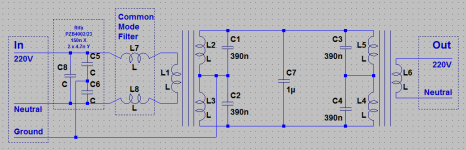
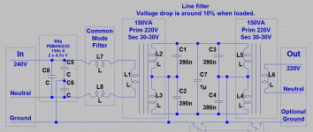
The cap should be line to line on the secondary and at least 1uF, probably more like 10 uF. Use a good crossover cap since it will have pretty high current and needs low esr/z at high frequencies to work. The connection to grounds wont help since the source voltage of the noise is pretty high and the impedance is high. Adding some additional impedance in series doesn't help. However this is where shunt impedance helps a lot. Two noise sources need to be addressed- common mode and normal/differential mode. The common mode is more difficult since its source Z is much higher.
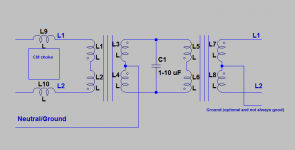
Here is a take on a revision to the isolation. Move the chokes to the primary to reduce the noise into the first transformer. Tie a ground from the CT of the secondary back to the outside ground to provide a shunt path for the CM noise. A big cap in the middle to shunt the normal mode noise. No connection to ground on the secondary side (at least none shared with a power or safety /neutral return). If the DUT is tied to the noisy power system the differential between the grounds will push noise back into the test system. In that case tie the chassis ground of the scope/whatever to a ground on the chassis with a separate wire. Don't use the probe return for this. The separate ground wire seems essential for very low noise measurements otherwise any ground currents from transformer leakages etc. get mixed into the signal.
BE VERY CAREFUL! The voltages and power here can be lethal. This is not a place to be sloppy (not that you would be but we have a big audience). I don't think the magnetic coupling between the two transformers is the dominant issue yet.
Attachments
Demian....
--->
From my #199
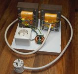
"I have filters on the input and output. The primary benefit to going low voltage step-down/up is to have a filter that can be in between the back-to-back secondaries and use low voltage parts. Here I am using 4 mfd of film between the xfmr's. Your values can vary depending on the transformers used (L). "
Thx-RNMarsh
Same. same.
FdW -- try it exactly as I suggested. But the transformers you use aren't as effective as the ones I use. They are important to get best results. BTW - This design I show - with the transformers I show - has been sold as a commercial product. Shown was the prototype. Works very well.
But there are a lot of paths that ground can take... and I can't see what you are doing.
Last edited:
The input has a plug (in my application) that could be plugged either way (neutral and phase can be swapped), this is why I never will connect the neutral/phase to the primary center tab (it galvanic connects to every thing else in the circuit, including the output). One of the things that I want to do is; create total galvanic separation from the mains.
Then you didnt put the transformers at right angles, as I showed. Also there is straight pass thru of noise on your transformers. You need low stray C coupling between windings. But thats another part of the story on how to make isolation that works for you. Not any transformer works best here for isolation.
Next update I will have placed the transformers at right angles. I'm sure I can improve on transformer quality, but the point is that I wanted to make good use of these (very old and disused) transformers (they have been sitting here for about 40 years doing nothing).
Last edited:
BE VERY CAREFUL! The voltages and power here can be lethal. This is not a place to be sloppy (not that you would be but we have a big audience). I don't think the magnetic coupling between the two transformers is the dominant issue yet.
YES! I know
but it is always good to remind people of this!And the circuit, so you can avoid building one
One more thing to report
From this circuit I did remove the mains and equipment ground connections, this change lowered noise on the scope with about 50%. From this I conclude that removing the ground connections is a good idea yes. float the ground and isolate the ground are ways to help solving your particular ground related issues. Do both. have you looked at any EMI/RFI issues from equipment/lighting ? You may have multiple paths to tend to.
Other than ground issues.... Have you characterized any offending 'noise' frequencies? This is where a spectrum analyzer comes in handy with appropriate probes. They are a clue as to where the interfence is coming from and then the specific solution.
Thx-RNMarsh
Other than ground issues.... Have you characterized any offending 'noise' frequencies? This is where a spectrum analyzer comes in handy with appropriate probes. They are a clue as to where the interfence is coming from and then the specific solution.
Thx-RNMarsh
Last edited:
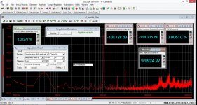
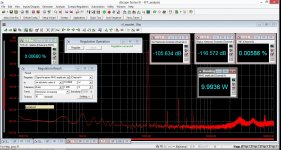
Thanks richard ! I built up your circuit but left the center taps disconnected. I found that it resulted in a very significant improvement. Here are some pictures of the results @10W 1khz from an amp that I am designing. I have a lot of HF crud in my house and that was very significantly reduced using the isolater. Interestingly i found improvements in the LF side as well although I am mystified why that might be the case - note that I did *NOT* isolate the grounds so the ground is left as-is without any connection to the rest of your isolator. I did not find much difference either way and did not want to get fried in case I had an accident.
For the caps I used an el-cheapo 1.5uF mains rated cap and a not-quite-so-cheap wima 0.47uF. I left space to add more bits inbetween but this will do for now.
With the signal generator on my analyzer turned off, i found that noise fell from 250uV (80khz bw) to 60 uV. I wonder if a simple cap across the amps PSU primary will do but i will try that out later when this goes into a chassis.
Thanks again.
Attachments
Last edited:
Now think about the audio amplifier that does not use an isolation transformer. You may be listening to more noise and distortion than you tested using isolation transformers . I use isolation transformers to power the music source and another for the DAC/preamp.
Thx-RNMarsh
Thx-RNMarsh
Last edited:
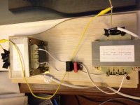
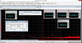
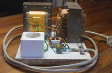
This is my 'final' version, it cleans up the scope's (I did build two) very visual, the visual noise (when I connect a DUT ground only) goes down by about 70%. Next I will get rid of the SMPS's of the LED lighting in my lab for this I will build a normal (non SMPS) supply of 12Vdc/4A, this must be done because switching the LED light off removes all other visual noise from the scopes.
Jan, to answer your remark about voltage drop, the measured voltage drop under load is about 10% this is within specification of all the measuring equipment that I have connected. An input voltage of 240Vac gives an (loaded 150VA scope spec) output voltage of 220Vac (you must make sure that the connected equipment works fine at about 200Vac). When building a filter like this one needs to check the voltage ratings for the equipment that will be connected.
In my setup I did not connect the output ground's, I do like the total galvanic separation that this gives, no possibilities of ground loops, and it is totally safe to hook the scopes at any point in the circuit (there is also no possibility of shorts via a shared ground). That said, be careful mixing to much, it is easy to loose track of what connects to what when selecting different ground references are being selected.
Thanks to RNMash and everyone else.
version, it cleans up the scope's (I did build two) very visual, the visual noise (when I connect a DUT ground only) goes down by about 70%. Next I will get rid of the SMPS's of the LED lighting in my lab for this I will build a normal (non SMPS) supply of 12Vdc/4A, this must be done because switching the LED light off removes all other visual noise from the scopes.Jan, to answer your remark about voltage drop, the measured voltage drop under load is about 10% this is within specification of all the measuring equipment that I have connected. An input voltage of 240Vac gives an (loaded 150VA scope spec) output voltage of 220Vac (you must make sure that the connected equipment works fine at about 200Vac). When building a filter like this one needs to check the voltage ratings for the equipment that will be connected.
In my setup I did not connect the output ground's, I do like the total galvanic separation that this gives, no possibilities of ground loops, and it is totally safe to hook the scopes at any point in the circuit (there is also no possibility of shorts via a shared ground). That said, be careful mixing to much, it is easy to loose track of what connects to what when selecting different ground references are being selected.
Thanks to RNMash and everyone else.
Attachments
Last edited:
This is my 'final'
Jan, to answer your remark about voltage drop, the measured voltage drop under load is about 10% this is within specification of all the measuring equipment that I have connected. An input voltage of 240Vac gives an (loaded 150VA scope spec) output voltage of 220Vac (you must make sure that the connected equipment works fine at about 200Vac). When building a filter like this one needs to check the voltage ratings for the equipment that will be connected.
In my setup I did not connect the output ground's, I do like the total galvanic separation that this gives, no possibilities of ground loops, and it is totally safe to hook the scopes at any point in the circuit (there is also no possibility of shorts via a shared ground). That said, be careful mixing to much, it is easy to loose track of what connects to what when selecting different ground references are being selected.
Thanks to RNMash and everyone else.
This is really nice, and it is good to see it is effective. I have two questions, hope I didn't miss their answers earlier in the thread.
The two optional ground switches provide nice flexibility. What is your general experience on which switch positions work best?
Just for added safety, have you thought about the possibility of connecting back-back paralleled diodes from the input safety ground to the output safety ground, maybe switchable? I realize they would add some stray capacitance depending on their size, but this might be smaller than the strays going through the transformers anyway.
Also for safety, I wonder if the mains GFI or a GFI on the output side could play a role in increased safety in the event of some fault (definitely not sure about the latter). There might be a way to sense a fault and "deliberately" trip the mains GFI in a relatively non-intrusive way, since it takes little current through the safety ground to do so.
Cheers,
Bob
- Home
- Design & Build
- Equipment & Tools
- QuantAsylum QA400 and QA401