I'm sure the Agilent power supply is not a $39 generic ATX supply. Most of the problems I have seen come from a mix of grounding issues and the common ground of the PC Chassis and the stuff under test. Switcher supplies can work fine and be low noise (my Tek scopes all have low noise switchers from the '70s) but on cheap PC's the goal is to meet FCC and no more. They usually have a noise filter that ensures any noise in the system or on the power line will get coupled back to ground. If you are looking at a grounded preamp with a grounded PC the ground currents in each ground return will be shared and show up in the readings if the system can't tell the difference. Depending on the application and rules the line filters can dump as much as 1 mA into the safety ground.
Maybe Richard can contribute an article to Linear Audio on the noise and grounding issues in measuring audio?
Maybe Richard can contribute an article to Linear Audio on the noise and grounding issues in measuring audio?
I do have a 230>115 isolation transformer that I use for my 115V solder station and that has sufficient capacity.
So I will try to run the PC from that one (I know, not optimised for isolation but it's free as I have it already). The PC should be multi-mains anyway so run on 115V.
An other option would be to run the PC from a UPS. Would that not work?
jan
So I will try to run the PC from that one (I know, not optimised for isolation but it's free as I have it already). The PC should be multi-mains anyway so run on 115V.
An other option would be to run the PC from a UPS. Would that not work?
jan
Last edited:
Maybe Richard can contribute an article to Linear Audio on the noise and grounding issues in measuring audio?
That would be great! Richard? Please?
jan
Now I checked (the transformers) and they are Amron P287's 220Vin 2 time 20-24-30V 2.5A. I could connect the secondary's in series, lets say 60V from the input transformer and 54V on the output transformer. Between the 60-54 connection an common mode filter could be added. Would that be worth a try?
Grounding 
I did have responsibility for several major projects which had massive potential for ground problems. The equipment in the Operations/Control console, multiple high speed number crunching computer room, high power supplies, diagnostics/measurment equipment, etc. And, it better work right when you are done --- or You are done. Take a look at the left-right isle of equipment racks to be filled from floor to ceiling with electronics... thats a 10KW ultra-isolation transformer hanging from the ceiling to power the racks. Computer grounding, power grounding, signal and control routing, grounding, shielding. Shielded cables/routing/grounding/isolation. Those row of power supplies are high power Arc welding supplies pressed into service for the experimental machine. You had to design several grounding systems and shielding etc.
Audio T&M? IMO it is the basic responsibility of the test equipment maker to make his products immune to ground issues in this case. Especially if he expects it to be powered from the PC. That means clean DC supply and using opto-isolation for the data I/O etc etc. Go to the mfr of the ADC instrument and get him to do it right. Or, you will have to do these things via mods and add-on circuitry.
Thx-RNMarsh
Last edited:
Three levels of changes to the 339A oscillators. Level one is replace most everything and get an average of what is shown for THD is -125dB. The last one has only has the oscillator opamp and driver/buffer opamp and a cap and trimmer R. All else stock. The middle osc had a few more opamps/capacitor changes and the analyzer section had opamps and parts changed.
If you just want an oscillator with a minimum of changes, it gets you over -110dB. The design has its limitations.
THx-RNMarsh


[These are tuned for over-all compromise across a broad range of freqs.]
If you just want an oscillator with a minimum of changes, it gets you over -110dB. The design has its limitations.
THx-RNMarsh
[These are tuned for over-all compromise across a broad range of freqs.]
Last edited:
Jan-
I realized after all the back and forth that the problem you are trying to solve is what the interface I designed is intended to solve. The differential inputs, dynamic balanced outputs and separate ground connections remove the ground noise from the measurement loop.
You can still get problems from ground noise but its easier to control and avoid with a separate ground connection.
That would be great! Richard? Please?
jan
OK. But not mostly about grounding per se .... isolation from ground and filtering. Could be a short description of concepts with some data to back it up. Some of the newer and more interesting solutions. Rather than what has been re-hashed a lot. I'll throw in some consulting examples of very weird problems and the solution I used. One of the rolls of consultant is that you get the hard ones.... after all the easy ideas and solutions have been tried. But, dont ask me 'when'. [dont worry, it will happen]
Thx-RNMarsh
Last edited:
OK. But not mostly about grounding per se .... isolation from ground and filtering. Could be a short description of concepts with some data to back it up. Some of the newer and more interesting solutions. Rather than what has been re-hashed a lot. I'll throw in some consulting examples of very weird problems and the solution I used. One of the rolls of consultant is that you get the hard ones.... after all the easy ideas and solutions have been tried. But, dont ask me 'when'. [dont worry, it will happen]
Thx-RNMarsh
Looking forward!
Jan-
I realized after all the back and forth that the problem you are trying to solve is what the interface I designed is intended to solve. The differential inputs, dynamic balanced outputs and separate ground connections remove the ground noise from the measurement loop.
You can still get problems from ground noise but its easier to control and avoid with a separate ground connection.
Yes that's something I'm going to try!
You could use the transformers back-2-back but the output 220V will be (significantly) lower I'm afraid.
jan
I'm sure many have thought of this, but what about using the two primary windings found on most transformers these days to do 120 to 120 V isolation?
(those are the windings we connect in parallel for 120V mains and in series for 240V mains.)
I'm guessing the usable VA would be about half what the transformer is rated for, but I'm not sure (might be better than 1/2 if it is the core that is limiting the VA - only maybe - not a transformer expert).
Cheers,
Bob
You could use the transformers back-2-back but the output 220V will be (significantly) lower I'm afraid.
jan
The common mode and other filter parts are ordered and I will report on my progress with this test (most probably after the next weekend). The transformers will be coupled: line 220-in 60-out common-mode-filter 60-in 220-out to the scope. The output voltage will be lower than 220V but that is no problem, the scope, a Tek 2252, is specified for 90-250Vac 150VA 100Watt, and the transformers are 60V 2.5A (that is 150VA).
Frank (?) I'd be interested how that goes.
Do you have a source of interference that you can use to see how much your setup blocks it?
Are the transformers toriods? Regular E-I would provide more isolation from mains-borne junk than toroids would.
jan
Yes, I have a few cheap (actually they did cost 6$ for each 50W supply) SMPS's to power some LED strings, and these SMPS's are very noisy
I can test SMPS's on/of and filter on/off, lets see what happens. The transformers are E-I style.Regards,
Frans.
Last edited:
For Linear Audio mag -
Here it is all done for you--->
I have filters on the input and output. The primary benefit to going low voltage step-down/up is to have a filter that can be in between the back-to-back secondaries and use low voltage parts. Here I am using 4 mfd of film between the xfnr's. Your values can vary depending on the transformers used (L).
Shown is the unit I made... gutted a commercial ac line filter -- using its protection circuitry and other features and placed two such Isolation-Filters in it. One for the DAC and one for the source. The whole thing has been in continuous operation for at least 10 years. I power my super Iso-Filters, as I call them, with a super line regulator {Mfr by ELGAR].
This would be very helpful for anyone with noise and ground issues.
[Those in countries of nominal 230vac, can just ground the center taps or not-switchable] .
Thx-RNMarsh


Source for Isolation-Filters:
.jpg")
Here it is all done for you--->
I have filters on the input and output. The primary benefit to going low voltage step-down/up is to have a filter that can be in between the back-to-back secondaries and use low voltage parts. Here I am using 4 mfd of film between the xfnr's. Your values can vary depending on the transformers used (L).
Shown is the unit I made... gutted a commercial ac line filter -- using its protection circuitry and other features and placed two such Isolation-Filters in it. One for the DAC and one for the source. The whole thing has been in continuous operation for at least 10 years. I power my super Iso-Filters, as I call them, with a super line regulator {Mfr by ELGAR].
This would be very helpful for anyone with noise and ground issues.
[Those in countries of nominal 230vac, can just ground the center taps or not-switchable] .
Thx-RNMarsh
Source for Isolation-Filters:
Last edited:
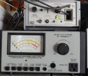
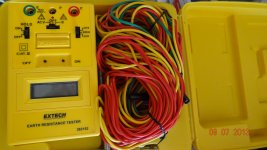
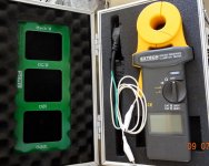
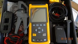
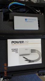
For those who really want to get deep into it, you will eventually need a network analyzer, and a spectrum analyzer. Plus: some HV probes and at least some idea of what your ground is actually doing, regarding leakage current to ground, Z of earth and Z of ground paths and types of noise (CM or DM etc). Such as:
Attachments
Last edited:
- Home
- Design & Build
- Equipment & Tools
- QuantAsylum QA400 and QA401